2005 MITSUBISHI LANCER break
[x] Cancel search: breakPage 96 of 788
IGNITION SYSTEM
ENGINE ELECTRICAL16-32
ON-VEHICLE SERVICE
IGNITION COIL (WITH BUILT-IN POWER
TRANSISTOR) CHECK
M1163001200324
Check by the following procedure, and replace if
there is a malfunction.
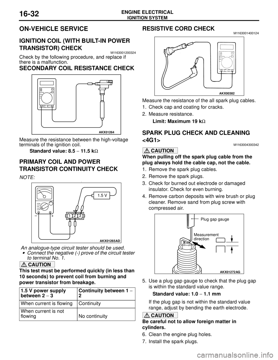
SECONDARY COIL RESISTANCE CHECK
Measure the resistance between the high-voltage
terminals of the ignition coil.
Standard value: 8.5 − 11.5 kΩ
PRIMARY COIL AND POWER
TRANSISTOR CONTINUITY CHECK
NOTE: .•
An analogue-type circuit tester should be used.
•Connect the negative (-) prove of the circuit tester
to terminal No. 1.
CAUTION
This test must be performed quickly (in less than
10 seconds) to prevent coil from burning and
power transistor from breakage.
RESISTIVE CORD CHECKM1163001400124
Measure the resistance of the all spark plug cables.
1. Check cap and coating for cracks.
2. Measure resistance.
Limit: Maximum 19 kΩ
SPARK PLUG CHECK AND CLEANING
<4G1>
M1163004300342
CAUTION
When pulling off the spark plug cable from the
plug always hold the cable cap, not the cable.
1. Remove the spark plug cables.
2. Remove the spark plugs.
3. Check for burned out electrode or damaged
insulator. Check for even burning.
4. Remove carbon deposits with wire brush or plug
cleaner. Remove sand from plug screw with
compressed air.
5. Use a plug gap gauge to check that the plug gap
is within the standard value range.
Standard value: 1.0 − 1.1 mm
If the plug gap is not within the standard value
range, adjust by bending the earth electrode.
CAUTION
Be careful not to allow foreign matter in
cylinders.
6. Clean the engine plug holes.
7. Install the spark plugs. 1.5 V power supply
between 2 − 3Continuity between 1 −
2
When current is flowing Continuity
When current is not
flowing No continuity
AKX01264
AKX01265AD
1.5 V
123 +
–
AKX00382
AKX01272
AG
Plug gap gauge
Measurement
direction
Page 191 of 788

Page 192 of 788

STRUT ASSEMBLY
FRONT SUSPENSION33-10
>>B<< STRUT NUT (SELF-LOCKING NUT)
INSTALLATION
1. Ensure that the bearing is seated correctly.
CAUTION
Do not use an impact wrench to tighten the bolt
of special tool spring compressor body
(MB991237), otherwise the special tool will break.
2. Install following special tools to the strut assembly
same as its removal.
•MB991237: Spring Compressor Body
•MB991238: Arm Set
3. While the coil spring is being compressed by the
special tools, temporarily tighten the strut nut
(self-locking nut).
4. Align the hole in the strut spring lower seat with
the hole in the spring upper seat.
NOTE:
Using a rod as shown facilitates the alignment.5. Align lower end of the coil spring with the groove
in the spring lower seat, and then loosen the
special tools.CAUTION
Do not use an impact wrench to tighten the
self-locking nut, otherwise the strut nut
(self-locking nut) will be damaged.
6. Using following special tools, tighten the strut nut
(self-locking nut) to 60 ± 10 N⋅m.
•MB991681: Wrench
•MB991682: Socket
INSPECTIONM1332001400188
•Check the strut bearing for wear or rust.
•Check the rubber parts for damage or
deterioration.
•Check the coil spring for deformation,
deterioration or damage.
•Check the strut for deformation.
AC001085 AB
MB991238
MB991237
AC006091 AB
Rod
AC006091 AB
MB991681 MB991682
Page 194 of 788

Page 206 of 788

ON-VEHICLE SERVICE
REAR SUSPENSION34-6
If camber is not within the standard value, adjust by
following procedures.
1. Disconnect the conjunction of the control link and
the trailing arm.
2. Carry out adjustment by turning the camber
adjusting bolt (lower arm assembly mounting bolt
which is located on the inner side of the body).
NOTE: .
•LH: Clockwise viewed from the front → (+)
camber
•RH: Clockwise viewed from the front → (-)
camber
•The scale has gradations of approximately 14'.
CAUTION
To prevent bushings from breakage, the
connecting bolt should be temporarily tightened,
and then fully tightened to 90 ± 10 N⋅m with the
vehicle on the earth in the unladen condition.
3. Tighten the control link to the trailing arm.
4. After adjusting the camber, the toe should be
adjusted.
TOE-IN
Standard value:
At the centre of tyre tread: 3 ± 2 mm
Toe angle (per wheel): 0°08' ± 05'If toe-in is not within the standard value, adjust by
following procedures.
CAUTION
To prevent bushings from breakage, the control
link mounting nut should be temporarily
tightened, and then fully tightened to 120 ± 10
N⋅m with the vehicle on the earth in the unladen
condition.
Carry out adjustment by turning the toe adjusting bolt
(control link mounting bolt which is located on the
inner side of the body).
NOTE: .
•LH: Clockwise viewed from the front → Toe-in
•RH: Clockwise viewed from the front → Toe-out
•Turning the toe adjusting bolt by one groove of
the scale, toe can be changed approximately 2.6
mm (single side toe angle equivalent to 16').
CONTROL LINK PILLOW BALL BUSHING
AXIAL PLAY CHECK
M1341018500011
1. Raise the vehicle.
2. Move the control link up and down with your
hands to check for an excessive play in the axial
direction of the pillow ball bushing. If there is an
excessive play, replace the control link (Refer to
P.34-8).
AC006159AC
Camber adjusting bolt
Lower arm
assembly
AC006160
AC
Connecting bolt
AC006145AD
Control link Toe adjusting boltControl link
Control link
mounting nut
AC304398ABControl link pillow ball bushing
Front of
vehicle
Page 209 of 788

Page 218 of 788

Page 219 of 788
SHOCK ABSORBER ASSEMBLY
REAR SUSPENSION34-19
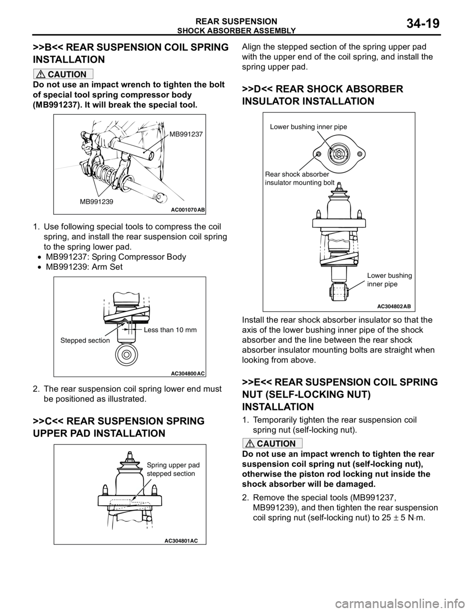
>>B<< REAR SUSPENSION COIL SPRING
INSTALLATION
CAUTION
Do not use an impact wrench to tighten the bolt
of special tool spring compressor body
(MB991237). It will break the special tool.
1. Use following special tools to compress the coil
spring, and install the rear suspension coil spring
to the spring lower pad.
•MB991237: Spring Compressor Body
•MB991239: Arm Set
2. The rear suspension coil spring lower end must
be positioned as illustrated.
>>C<< REAR SUSPENSION SPRING
UPPER PAD INSTALLATION
Align the stepped section of the spring upper pad
with the upper end of the coil spring, and install the
spring upper pad.
>>D<< REAR SHOCK ABSORBER
INSULATOR INSTALLATION
Install the rear shock absorber insulator so that the
axis of the lower bushing inner pipe of the shock
absorber and the line between the rear shock
absorber insulator mounting bolts are straight when
looking from above.
>>E<< REAR SUSPENSION COIL SPRING
NUT (SELF-LOCKING NUT)
INSTALLATION
1. Temporarily tighten the rear suspension coil
spring nut (self-locking nut).
CAUTION
Do not use an impact wrench to tighten the rear
suspension coil spring nut (self-locking nut),
otherwise the piston rod locking nut inside the
shock absorber will be damaged.
2. Remove the special tools (MB991237,
MB991239), and then tighten the rear suspension
coil spring nut (self-locking nut) to 25 ± 5 N⋅m.
AC001070
MB991237
MB991239
AB
AC304800AC
Less than 10 mm
Stepped section
AC304801AC
Spring upper pad
stepped section
AC304802
Lower bushing inner pipe
Rear shock absorber
insulator mounting bolt
AB
Lower bushing
inner pipe