2005 MITSUBISHI LANCER Strut
[x] Cancel search: StrutPage 57 of 788

INLET MANIFOLD
INTAKE AND EXHAUST15-5
INLET MANIFOLD
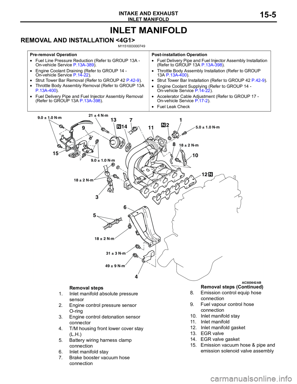
REMOVAL AND INSTALLATION <4G1>M1151003000749
Pre-removal Operation
•Fuel Line Pressure Reduction (Refer to GROUP 13A -
On-vehicle Service P.13A-389).
•Engine Coolant Draining (Refer to GROUP 14 -
On-vehicle Service P.14-22).
•Strut Tower Bar Removal (Refer to GROUP 42 P.42-9).
•Throttle Body Assembly Removal (Refer to GROUP 13A
P.13A-400).
•Fuel Delivery Pipe and Fuel Injector Assembly Removal
(Refer to GROUP 13A P.13A-398).Post-installation Operation
•Fuel Delivery Pipe and Fuel Injector Assembly Installation
(Refer to GROUP 13A P.13A-398).
•Throttle Body Assembly Installation (Refer to GROUP
13A P.13A-400).
•Strut Tower Bar Installation (Refer to GROUP 42 P.42-9).
•Engine Coolant Supplying (Refer to GROUP 14 -
On-vehicle Service P.14-22).
•Accelerator Cable Adjustment (Refer to GROUP 17 -
On-vehicle Service P.17-2).
•Fuel Leak Check
AC303642AB
15
3
6
5
412 10 71
2
11
913
14
21 ± 4 N·m
9.0 ± 1.0 N·m
9.0 ± 1.0 N·m
18 ± 2 N·m
18 ± 2 N·m18 ± 2 N·m5.0 ± 1.0 N·m
31 ± 3 N·m
49 ± 9 N·m
N
N
N
8
Removal steps
1. Inlet manifold absolute pressure
sensor
2. Engine control pressure sensor
O-ring
3. Engine control detonation sensor
connector
4. T/M housing front lower cover stay
(L.H.)
5. Battery wiring harness clamp
connection
6. Inlet manifold stay
7. Brake booster vacuum hose
connection8. Emission control equip hose
connection
9. Fuel vapour control hose
connection
10. Inlet manifold stay
11. Inlet manifold
12. Inlet manifold gasket
13. EGR valve
14. EGR valve gasket
15. Emission vacuum hose & pipe and
emission solenoid valve assembly Removal steps (Continued)
Page 58 of 788

INLET MANIFOLD
INTAKE AND EXHAUST15-6
REMOVAL AND INSTALLATION <4G6>M1151003001236
Pre-removal Operation
•Fuel Line Pressure Reduction (Refer to GROUP 13A -
On-vehicle Service P.13A-389).
•Engine Coolant Draining (Refer to GROUP 14 -
On-vehicle Service P.14-22).
•Strut Tower Bar Removal (Refer to GROUP 42 P.42-9).
•Throttle Body Assembly Removal (Refer to GROUP 13B
P.13B-336).
•Fuel Delivery Pipe and Fuel Injector Assembly Removal
(Refer to GROUP 13B P.13B-334).Post-installation Operation
•Fuel Delivery Pipe and Fuel Injector Assembly Installation
(Refer to GROUP 13B P.13B-334).
•Throttle Body Assembly Installation (Refer to GROUP
13B P.13B-336).
•Strut Tower Bar Installation (Refer to GROUP 42 P.42-9).
•Engine Coolant Supplying (Refer to GROUP 14 -
On-vehicle Service P.14-22).
•Accelerator Cable Adjustment (Refer to GROUP 17 -
On-vehicle Service P.17-2).
•Fuel Leak Check
AC303657
9.0 ± 1.0 N·m11 ± 1 N·m
20 ± 2 N·m
31 ± 3 N·m 36 ± 6 N·m
20 ± 2 N·m
20 ± 2 N·m
36 ± 6 N·m
36 ± 6 N·m
11
9 10 212
N1413N
AB
5.0 ± 1.0 N·m
3
1
11 ± 1 N·m
4
N
13 ± 1 N·m
5
6
(Engine oil)
7
8
Removal steps
1. Emission control equip hose
connector
2. Brake booster vacuum hose
connection
3. Earth cable connection4. Engine control detonation sensor
connector
5. Engine oil level gauge and guide
assembly
6. Engine oil filler O-ring
7. Emission vacuum hose connectionRemoval steps (Continued)
Page 77 of 788

CHARGING SYSTEM
ENGINE ELECTRICAL16-13
REMOVAL AND INSTALLATION <4G6>M1161001400559
Pre-removal Operation
•Under Cover Removal
•Strut Tower Bar Removal (Refer to GROUP 42 P.42-9).
•Drive Belt Removal (Refer to GROUP 11C - Crankshaft
Pulley P.11C-16).
•Air Cleaner Assembly Removal (Refer to GROUP 15
P.15-3).Post-installation Operation
•Air Cleaner Assembly Installation (Refer to GROUP 15
P.15-3).
•Drive Belt Installation (Refer to GROUP 11C - Crankshaft
Pulley P.11C-16).
•Strut Tower Bar Installation (Refer to GROUP 42 P.42-9).
•Drive Belt Tension Adjustment (Refer to GROUP 11C -
On-vehicle Service P.11C-7).
•Under Cover Installation
AC303826
1
2
318 ± 3 N·m
AB
Removal steps
1. Shift cable connection<>2. shift cable and shift cable bracket
assembly
3. Vehicle speed sensor connectorRemoval steps (Continued)
Page 134 of 788

GENERAL INFORMATION
FRONT AXLE26-2
GENERAL INFORMATION
M1261000100347
The front axle consists of front hubs, knuckles, wheel
bearings and driveshafts, and has the following
features:
•The wheel bearing is a double-row angular
contact ball bearing which incorporates the oil
seals and is highly resistant to thrust loads.
•The driveshaft incorporates BJ-TJ type constant
velocity joints with high transmission efficiency for
low vibration and noise.•The dynamic damper has been mounted on the
driveshaft to reduce differential gear noise.
•ABS rotor for detecting the wheel speed is
press-fitted to the BJ.
NOTE: .
•TJ: Tripod Joint
•BJ: Birfield Joint
SPECIFICATIONS
CONSTRUCTION DIAGRAM
Item 1.3L, 1.6L 2.0L
Wheel bearing Type Double-row angular contact ball bearing
Bearing (OD x ID) mm 80 x 40 80 x 40
Driveshaft Joint type Outer BJ BJ
Inner TJ TJ
Length (joint to joint) ×
diameter mm LH 375.9 × 23.2 375.9 × 23.2
RH 699 × 23.2 (1.6L-M/T),
703.2 × 22 (1.3L-M/T,
1.6L-A/T)700 × 23.2
AC303569
Front hubKnuckleStrut assembly
TJ (LH)
Drive shaft (LH)
Dynamic damper
BJ
Wheel bearing
Drive shaft (RH) TJ (RH)
AB
ABS rotorDynamic damper
Page 140 of 788

FRONT AXLE HUB ASSEMBLY
FRONT AXLE26-8
FRONT AXLE HUB ASSEMBLY
REMOVAL AND INSTALLATIONM1261001700353
CAUTION
•Do not strike the ABS rotors installed to the BJ outer race of drive shaft against other parts when
removing or installing the drive shaft. Otherwise the ABS rotors will be damaged.
•Be careful not to strike the pole piece at the tip of the front ABS sensor with tools during servicing
work.
Post-installation Operation
•Check the dust cover for cracks or damage by pushing it
with your finger.
AC209505
N
N
N
5
4 3 1 810
9 2 76
167 ± 9 N·m25 ± 5 N·m
108 ± 10 N·m245 ± 29 N·m
100 ± 10 N·m
AC
7
7
111213
Removal steps
1. Front ABS sensor
<>
2. Caliper assembly
<>
3. Brake disc
<
>>B<<5. Washer
>>A<<6. Self-locking nut (stabilizer bar
connection)
>>A<<7. Stabilizer rubber8. Collar
9. Lower arm connecting bolt
<
10. Self-locking nut (tie rod end
connection)
<
11 . D r i v e s h a f t
12. Nut (hub and knuckle to strut
connection)
13. Hub and knuckle
Removal steps (Continued)
Page 183 of 788

33-1
GROUP 33
FRONT
SUSPENSION
CONTENTS
GENERAL INFORMATION . . . . . . . .33-2
SERVICE SPECIFICATIONS . . . . . . .33-3
LUBRICANT . . . . . . . . . . . . . . . . . . . .33-3
SPECIAL TOOLS . . . . . . . . . . . . . . . .33-4
ON-VEHICLE SERVICE . . . . . . . . . . .33-5
FRONT WHEEL ALIGNMENT CHECK
AND ADJUSTMENT . . . . . . . . . . . . . . . . . . 33-5
LOWER ARM BALL JOINT AXIAL PLAY
CHECK . . . . . . . . . . . . . . . . . . . . . . . . . . . . 33-6
LOWER ARM BALL JOINT COVER
CHECK . . . . . . . . . . . . . . . . . . . . . . . . . . . . 33-6
STRUT ASSEMBLY . . . . . . . . . . . . . .33-7
REMOVAL AND INSTALLATION . . . . . . . . 33-7
INSPECTION . . . . . . . . . . . . . . . . . . . . . . . . 33-7
DISASSEMBLY AND REASSEMBLY . . . . . 33-8
INSPECTION . . . . . . . . . . . . . . . . . . . . . . . . 33-10
LOWER ARM . . . . . . . . . . . . . . . . . . .33-11
REMOVAL AND INSTALLATION . . . . . . . . 33-11
INSPECTION . . . . . . . . . . . . . . . . . . . . . . . . 33-12
LOWER ARM BALL JOINT COVER
REPLACEMENT . . . . . . . . . . . . . . . . . . . . . 33-12
LOWER ARM BUSHING (REAR)
REPLACEMENT . . . . . . . . . . . . . . . . . . . . . 33-13
STABILIZER BAR* . . . . . . . . . . . . . . .33-14
REMOVAL AND INSTALLATION . . . . . . . . 33-14
INSPECTION . . . . . . . . . . . . . . . . . . . . . . . . 33-17
WARNINGS REGARDING SERVICING OF SUPPLEMENTAL RESTRAINT SYSTEM (SRS) EQUIPPED VEHICLES
WARNING
•Improper service or maintenance of any component of the SRS, or any SRS-related component, can lead to
personal injury or death to service personnel (from inadvertent firing of the air bag) or to the driver and
paassenger (from rendering the SRS inoperative).
•Service or maintenance of any SRS component or SRS-related component must be performed only at an
authorized MITSUBISHI dealer.
•MITSUBISHI dealer personnel must thoroughly review this manual, and especially its GROUP 52B - Supplemental
Restraint System (SRS) before beginning any service or maintenance of any component of the SRS or any
SRS-related component.
NOTE
The SRS includes the following components: SRS air bag control unit, SRS warning light, front impact sensors, air bag module,
clock spring, and interconnecting wiring. Other SRS-related components (that may have to be removed/installed in connection
with SRS service or maintenance) are indicated in the table of contents by an asterisk (*).
Page 184 of 788

GENERAL INFORMATION
FRONT SUSPENSION33-2
GENERAL INFORMATION
M1332000100407
The front suspension is a McPherson strut with coil
spring. The shock absorber is gas-filled hydraulic
double-acting type.
CONSTRUCTION DIAGRAM
SPECIFICATIONS
COIL SPRING
NOTE: .
•The*mark indicates optional item.
AC304023
AC304022
AC304754
Lower arm assembly
Front axle No.1
crossmember Stabilizer bar
Strut (shock absorber) Coil spring
AB
Strut cover Strut damper
Item Sedan Wagon
Comfort Sport Comfort Sport
Wire diameter mm 13 13 13 <1600-M/T>
14 1600-A/T,
2000>14
13 <1600>
*
14 <2000>*
Average diameter mm 160 160 160 160
Free length mm 330 321 330 <1600-M/T>
338 <1600-A/T>
338 <2000>314 <1600>
321 <2000>
330 <1600>
*
338 <2000>*
Page 186 of 788

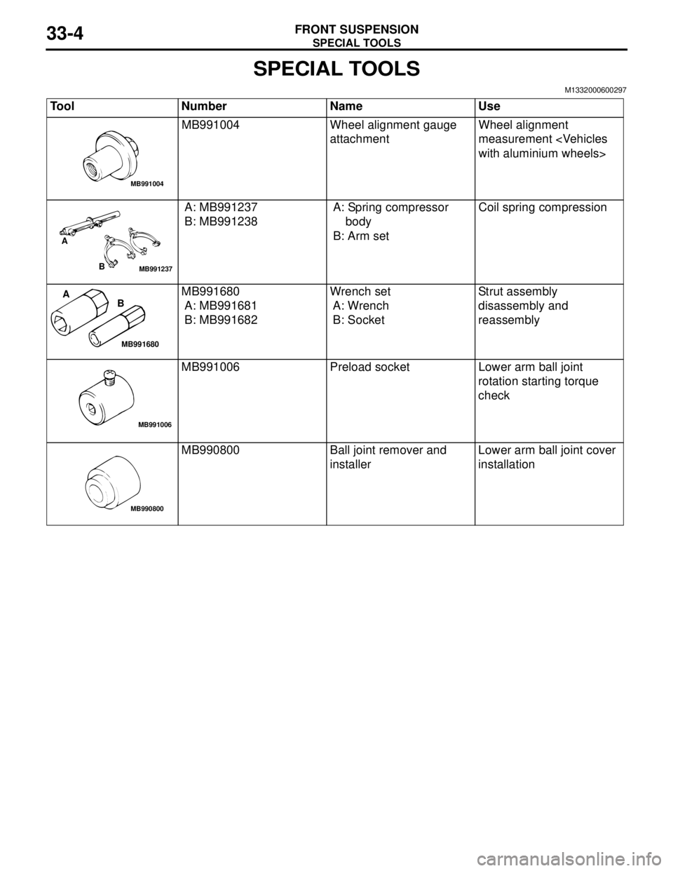
SPECIAL TOOLS
FRONT SUSPENSION33-4
SPECIAL TOOLS
M1332000600297
Tool Number Name Use
MB991004 Wheel alignment gauge
attachmentWheel alignment
measurement
A: MB991237
B: MB991238A: Spring compressor
body
B: Arm setCoil spring compression
MB991680
A: MB991681
B: MB991682Wrench set
A: Wrench
B: SocketStrut assembly
disassembly and
reassembly
MB991006 Preload socket Lower arm ball joint
rotation starting torque
check
MB990800 Ball joint remover and
installerLower arm ball joint cover
installation
MB991004
MB991237
A
B
MB991680
A
B
MB991006
MB990800