2005 MITSUBISHI LANCER Wheel
[x] Cancel search: WheelPage 167 of 788

TROUBLESHOOTING
WHEEL AND TYRE31-5
1. After balancing the wheel, loosen the wing nut
and turn the wheel 180° against the balancer's
hub. Then re-tighten the wing nut and check the
balance again. Repeat wheel balance if
necessary.
2. Turn the wheel again 180° against the balancer's
hub. If the wheel becomes out-of-balance each
time it is turned against the balancer's hub, the
wheel balancer may require calibration.
1. Mount an undamaged original-equipment alloy
rim and tyre assembly (wheel) onto your
off-the-car wheel balancer. Balance the wheel.
2. <
Loosen the balancer wing nut, rotate the wheel a
half-turn (180°), and retighten the nut. Recheck
the balance.
•If the imbalance is 5g or less, the zero calibration
is OK. Rebalance the wheel, then go to Step 4 to
check static balance.
•If the imbalance is more than 5g, go to Step 3.
3. Loosen the balancer wing nut, rotate the wheel
1/4 turn (90°), and retighten the nut. Recheck the
wheel balance.
•If the imbalance is 5g or less, the wheel may not
be centred on the balancer, or the balancing
cones, the cup, and/or wing nut are damaged,
dirty, or inappropriate for the wheel. You may
need to refer to the balancer manufacturer's
instructions to verify the correct attachments.
After making the necessary corrections, recheck
the wheel balance. If OK, then go to Step 4.•If the imbalance is more than 5g, the balancer
requires calibration. Contact the balancer
manufacturer for calibration by their repair
representative.
4. <
Attach a 5g weight to the outer rim. Recheck the
balancer. The balancer should detect 5 ± 2g of
imbalance 170 to 190° away from the 5g weight.
•If the imbalance is within specification, the static
balance calibration is correct. Go to Step 5 to
check the dynamic balance.
•If the imbalance is out of specification, the
balancer requires calibration. Contact the
balancer manufacturer for calibration by their
repair representative.
5. <
Attach a 5g weight to the inner rim at 180°
opposite the 5g weight that was added in Step 4.
Recheck the balance. The balancer should detect
5 ± 2g of imbalance 170 to 190° away from both
the inner and outer 5g weights.
•If the imbalance is within specification, the
dynamic balance calibration is correct. The
balancer calibration checks are complete.
•If the imbalance is out of specification, the
balancer requires calibration. Contact the
balancer manufacturer for calibration by their
repair representative.
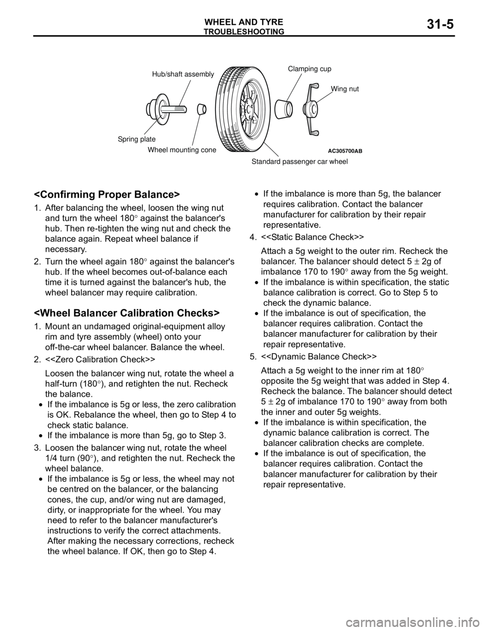
AC305700AB
Hub/shaft assemblyClamping cup
Wing nut
Standard passenger car wheel Wheel mounting cone Spring plate
Page 168 of 788

TROUBLESHOOTING
WHEEL AND TYRE31-6
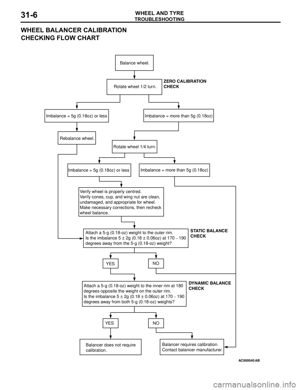
WHEEL BALANCER CALIBRATION
CHECKING FLOW CHART
AC000040
Balance wheel.
Rotate wheel 1/2 turn.
Imbalance = 5g (0.18oz) or lessImbalance = more than 5g (0.18oz)
Rebalance wheel.
Rotate wheel 1/4 turn.
Imbalance = 5g (0.18oz) or lessImbalance = more than 5g (0.18oz)
Verify wheel is properly centred.
Verify cones, cup, and wing nut are clean,
undamaged, and appropriate for wheel.
Make necessary corrections, then recheck
wheel balance.
Attach a 5-g (0.18-oz) weight to the outer rim.
Is the imbalance 5 ± 2g (0.18 ± 0.06oz) at 170
– 190
degrees away from the 5-g (0.18-oz) weight?
YESNO
Attach a 5-g (0.18-oz) weight to the inner rim at 180
degrees opposite the weight on the outer rim.
Is the imbalance 5 ± 2g (0.18 ± 0.06oz) at 170
– 190
degrees away from both 5-g (0.18-oz) weights?
YES NO
Balancer does not require
calibration.Balancer requires calibration.
Contact balancer manufacturer.ZERO CALIBRATION
CHECK
STATIC BALANCE
CHECK
DYNAMIC BALANCE
CHECK
AB
Page 169 of 788

ON-VEHICLE SERVICE
WHEEL AND TYRE31-7
ON-VEHICLE SERVICE
TYRE INFLATION PRESSURE CHECKM1311000900312
NOTE: For information on tyre inflation pressure,
refer to the label attached to the centre pillar on the
driver's side.
TYRE WEAR CHECKM1311001000334
Measure the tread depth of the tyres.
Minimum limit: 1.6 mm
If the remaining tread depth is less than the minimum
limit, replace the tyre.
NOTE: When the tread depth of the tyres is reduced
to 1.6 mm or less, wear indicators will appear.
WHEEL RUNOUT CHECKM1311001100353
Jack up the vehicle so that the wheels are clear of
the floor. While slowly turning the wheel, measure
wheel runout with a dial indicator.
Limit:
If wheel runout exceeds the limit, replace the wheel.
WHEEL AND TYRE
INSTALLATION SERVICE POINTM1311001300294
Tighten the wheel nuts to the specified torque.Tightening torque: 98 ± 10 N⋅m Item Steel wheel Aluminium
wheel
Radial runout mm 1.2 1.0
Lateral runout
mm1.2 1.0
ACX00651
ABLateralRadial
Page 178 of 788

CROSSMEMBER
POWER PLANT MOUNT32-8
INSTALLATION SERVICE POINTS
>>A<< ENGINE FRONT ROLL STOPPER
BRACKET INSTALLATION
Install the engine front roll stopper bracket so that its
hole points towards the front side of the vehicle.
>>B<< ENGINE MOUNTING CUSHION
STOPPER INSTALLATION <4G6>
Install the engine mounting cushion stopper as
shown.
CROSSMEMBER
REMOVAL AND INSTALLATIONM1321003200368
CAUTION
•Before removing the steering wheel and air bag module assembly, always refer to GROUP 52B -
Service Precautions P.52B-5, Air bag Module and Clock Spring P.52B-210. Also, set the front
wheels so that they are facing straight forward, and remove the ignition key. If you fail to do this,
the SRS clock spring will be damaged, causing the SRS air bag to be inoperative and serious
injury.
•*
1: Indicates parts which should be initially tightened, and then fully tightened after placing the
vehicle horizontally and loading the full weight of the engine on the vehicle body.
•*
2: Indicates parts which should be temporarily tightened, and then fully tightened with the vehicle
on the earth in the unladen condition.
AC005918Front of vehicleHoleACAC304315ABFront of vehicle
HoleEngine mounting
cushion stopper
Pre-removal Operation
•Centermember Removal (Refer to P.32-7).
•Front Exhaust Pipe Removal (Refer to GROUP 15,
Exhaust Pipe and Main Muffler P.15-11).
•Steering Wheel Air Bag Module Assembly Removal
(Refer to GROUP 37, Steering Wheel P.37-17).
•Power Steering Fluid Draining (Refer to GROUP 37,
On-vehicle Service P.37-13).Post-installation Operation
•Front Exhaust Pipe Installation (Refer to GROUP 15,
Exhaust Pipe and Main Muffler P.15-11).
•Centermember Installation (Refer to P.32-7).
•Clock Spring Centring (Refer to GROUP 52B, Air Bag
Modules and Clock Spring P.52B-210).
•Steering Wheel Air Bag Module Assembly Installation
(Refer to GROUP 37, Steering Wheel P.37-17).
•Power Steering Fluid Supplying (Refer to GROUP 37,
On-vehicle Service P.37-13).
•Power Steering Fluid Line Bleeding (Refer to GROUP 37,
On-vehicle Service P.37-13).
•Press the dust cover with a finger to check whether the
dust cover cracked or damaged.
•Checking Steering Wheel Position with Wheels Straight
Ahead.
•Front Wheel Alignment Check and Adjustment (Refer to
GROUP 33, On-vehicle Service P.33-5).
Page 183 of 788

33-1
GROUP 33
FRONT
SUSPENSION
CONTENTS
GENERAL INFORMATION . . . . . . . .33-2
SERVICE SPECIFICATIONS . . . . . . .33-3
LUBRICANT . . . . . . . . . . . . . . . . . . . .33-3
SPECIAL TOOLS . . . . . . . . . . . . . . . .33-4
ON-VEHICLE SERVICE . . . . . . . . . . .33-5
FRONT WHEEL ALIGNMENT CHECK
AND ADJUSTMENT . . . . . . . . . . . . . . . . . . 33-5
LOWER ARM BALL JOINT AXIAL PLAY
CHECK . . . . . . . . . . . . . . . . . . . . . . . . . . . . 33-6
LOWER ARM BALL JOINT COVER
CHECK . . . . . . . . . . . . . . . . . . . . . . . . . . . . 33-6
STRUT ASSEMBLY . . . . . . . . . . . . . .33-7
REMOVAL AND INSTALLATION . . . . . . . . 33-7
INSPECTION . . . . . . . . . . . . . . . . . . . . . . . . 33-7
DISASSEMBLY AND REASSEMBLY . . . . . 33-8
INSPECTION . . . . . . . . . . . . . . . . . . . . . . . . 33-10
LOWER ARM . . . . . . . . . . . . . . . . . . .33-11
REMOVAL AND INSTALLATION . . . . . . . . 33-11
INSPECTION . . . . . . . . . . . . . . . . . . . . . . . . 33-12
LOWER ARM BALL JOINT COVER
REPLACEMENT . . . . . . . . . . . . . . . . . . . . . 33-12
LOWER ARM BUSHING (REAR)
REPLACEMENT . . . . . . . . . . . . . . . . . . . . . 33-13
STABILIZER BAR* . . . . . . . . . . . . . . .33-14
REMOVAL AND INSTALLATION . . . . . . . . 33-14
INSPECTION . . . . . . . . . . . . . . . . . . . . . . . . 33-17
WARNINGS REGARDING SERVICING OF SUPPLEMENTAL RESTRAINT SYSTEM (SRS) EQUIPPED VEHICLES
WARNING
•Improper service or maintenance of any component of the SRS, or any SRS-related component, can lead to
personal injury or death to service personnel (from inadvertent firing of the air bag) or to the driver and
paassenger (from rendering the SRS inoperative).
•Service or maintenance of any SRS component or SRS-related component must be performed only at an
authorized MITSUBISHI dealer.
•MITSUBISHI dealer personnel must thoroughly review this manual, and especially its GROUP 52B - Supplemental
Restraint System (SRS) before beginning any service or maintenance of any component of the SRS or any
SRS-related component.
NOTE
The SRS includes the following components: SRS air bag control unit, SRS warning light, front impact sensors, air bag module,
clock spring, and interconnecting wiring. Other SRS-related components (that may have to be removed/installed in connection
with SRS service or maintenance) are indicated in the table of contents by an asterisk (*).
Page 185 of 788

SERVICE SPECIFICATIONS
FRONT SUSPENSION33-3
SERVICE SPECIFICATIONS
M1332000300586
NOTE: *: difference between right and left wheels must be less than 30'
LUBRICANT
M1332000400152
ItemStandard value
Toe-in At the centre of tyre tread mm 1 ± 2
Toe-angle (per wheel) 0°03' ± 06'
Toe-out angle on turns (inner wheel when outer wheel at 20°)21°42' ± 1°30'
Steering angle Inner wheel Comfort 39°30' ± 1°30'
Sport (LH drive vehicles) 33°40' +1°00'/-2°00'
Sport (RH drive vehicles) 37°00' +1°00'/-2°00'
Outer wheel (reference) Comfort 32°30'
Sport (LH drive vehicles) 28°46'
Sport (RH drive vehicles) 30°00'
Camber Comfort 0°05' ± 30'*
Sport -0°05' ± 30'*
Caster Comfort 2°45' ± 30'*
Sport 2°55' ± 30'*
Kingpin inclination Comfort 12°30' ± 1°30'
Sport 12°40' ± 1°30'
Lower arm ball joint rotation starting torque N⋅m0 − 3.9
Protruding length of stabilizer link thread part mm 22 ± 1.5
Item Specified lubricant Quantity
Lower arm ball joint Lip portion of ball joint cover Multipurpose grease SAE J310,
NLGI No.2 or equivalentAs required
Inside of ball joint cover
Page 186 of 788

SPECIAL TOOLS
FRONT SUSPENSION33-4
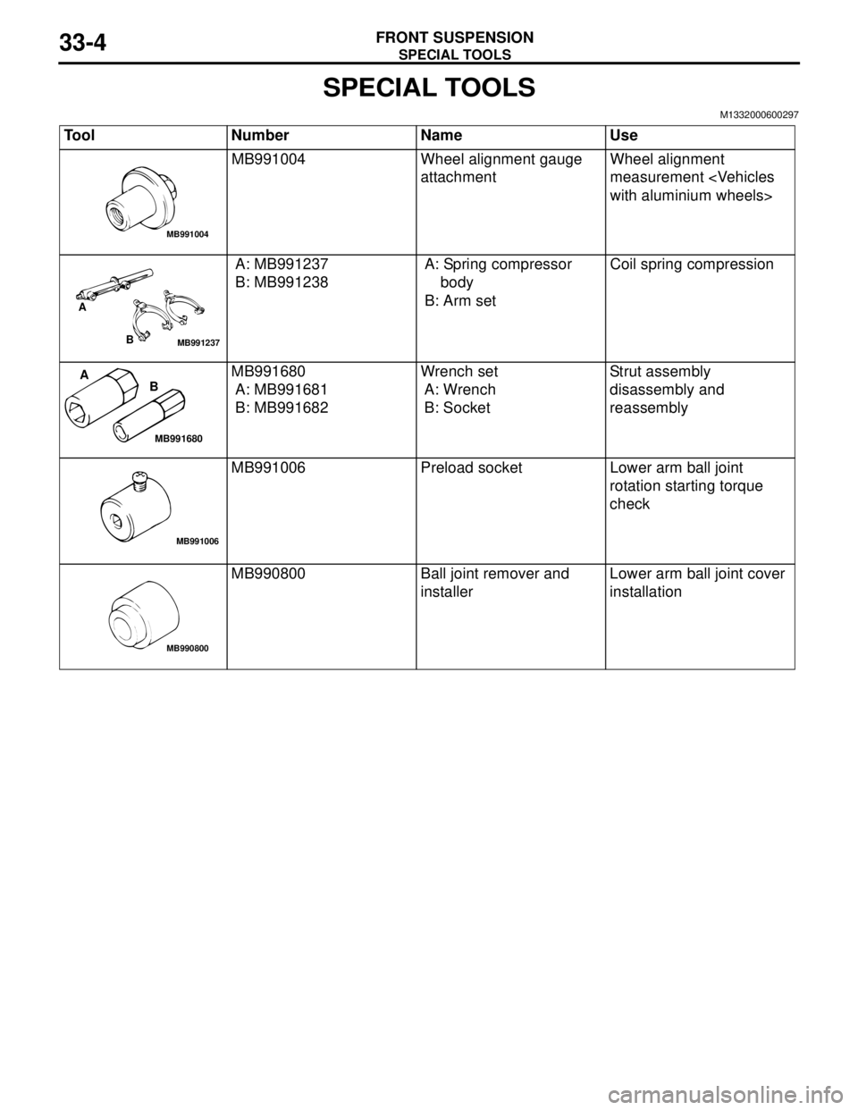
SPECIAL TOOLS
M1332000600297
Tool Number Name Use
MB991004 Wheel alignment gauge
attachmentWheel alignment
measurement
A: MB991237
B: MB991238A: Spring compressor
body
B: Arm setCoil spring compression
MB991680
A: MB991681
B: MB991682Wrench set
A: Wrench
B: SocketStrut assembly
disassembly and
reassembly
MB991006 Preload socket Lower arm ball joint
rotation starting torque
check
MB990800 Ball joint remover and
installerLower arm ball joint cover
installation
MB991004
MB991237
A
B
MB991680
A
B
MB991006
MB990800
Page 187 of 788

ON-VEHICLE SERVICE
FRONT SUSPENSION33-5
ON-VEHICLE SERVICE
FRONT WHEEL ALIGNMENT CHECK AND
ADJUSTMENT
M1331000900682
Measure wheel alignment with alignment equipment
on a level surface. The front suspension, steering
system, wheels, and tyres should be serviced to
normal condition before measuring wheel alignment.
TOE-IN
Standard value:
at the centre of tyre tread: 1 ± 2 mm
Toe angle (per wheel): 0°03' ± 06'
1. Adjust the toe-in by undoing the clip and lock nut,
and turning the left and right tie rod turnbuckles by
the same amount (in opposite directions). MB990883 Rear suspension bushing
arborLower arm bushing (rear)
removal and press-fitting
MB990972 Torsion bar bushing
remover base
MB990887 Ring
MB990890 Rear suspension bushing
base
MB991897 Ball joint remover Knuckle and tie rod end
ball joint disconnection
NOTE: Steering linkage
puller (MB990635 or
MB991113) is also
available to disconnect
knuckle and tie rod end
ball joint. Tool Number Name Use
MB990883
MB990971
MB990890
AC106827
AC006074AD
Lock nut
Clip