Page 146 of 788
Page 148 of 788
DRIVE SHAFT ASSEMBLY
FRONT AXLE26-16
CAUTION
•Do not pull on the drive shaft; doing so will
damage the TJ; be sure to use the pry bar.
•When pulling the drive shaft out from the
transmission, be careful that the spline part of
the drive shaft does not damage the oil seal.
3. Insert a pry bar between the transmission case
and the drive shaft, and then pry and remove the
drive shaft from the transmission.4. Use special tool plug (MB991460) to prevent the
entry of foreign material into the transmission
case.
CAUTION
Do not apply pressure to the wheel bearing by
the vehicle weight to avoid possible damage
when the drive shaft is removed. If, however,
vehicle weight must be applied to the bearing in
moving the vehicle, temporarily secure the wheel
bearing by using the following special tools.
•Spacer (MB991000)
•Front hub remover and installer (MB991017)AC100141
Transmission
TJ assembly
Pry bar
AG
AC102554
MB991460
AC
AC102555
AC
MB991017 MB991000
Page 171 of 788
32-1
GROUP 32
POWER PLANT
MOUNT
CONTENTS
GENERAL INFORMATION . . . . . . . .32-2
SERVICE SPECIFICATION . . . . . . . .32-3
SPECIAL TOOL . . . . . . . . . . . . . . . . .32-3
ENGINE MOUNTING . . . . . . . . . . . . .32-4
REMOVAL AND INSTALLATION . . . . . . . . 32-4
TRANSMISSION MOUNTING . . . . . .32-5
REMOVAL AND INSTALLATION . . . . . . . . 32-5
ENGINE ROLL STOPPER,
CENTERMEMBER . . . . . . . . . . . . . . .32-7
REMOVAL AND INSTALLATION . . . . . . . . 32-7
CROSSMEMBER . . . . . . . . . . . . . . . .32-8
REMOVAL AND INSTALLATION . . . . . . . . 32-8
Page 172 of 788
GENERAL INFORMATION
POWER PLANT MOUNT32-2
GENERAL INFORMATION
M1321000100340The engine mounting system employs the inertial
axis four-point suspension method, which is field
proven.
•The optimised locations of the front and rear roll
mounts well distribute their loads thereby
reducing engine idling vibrations.•The fore-and-aft, liquid-filled engine mount of
cylinder type is adopted to reduce engine shake
for improved riding comfort.
CONSTRUCTION DIAGRAM
AC107318
Y0290AU
AC303563
Engine front
mounting bracketTransmission mounting
body side bracket
Engine rear roll stopper bracket
Engine front roll stopper bracket
AB
Page 174 of 788
ENGINE MOUNTING
POWER PLANT MOUNT32-4
ENGINE MOUNTING
REMOVAL AND INSTALLATIONM1321001100440
CAUTION
*: Indicates parts which should be initially tightened, and then fully tightened after placing the vehicle
horizontally and loading the full weight of the engine on the vehicle body.
Pre-removal Operation
Raise the engine and transmission assembly until its weight
is not applied to the insulator, and support it securely.
AC303999AC303968AC304304
AB
<4G1> <4G6>
44 ± 10 N·m*
67 ± 7 N·m*
2N
3
44 ± 10 N·m*
67 ± 7 N·m*
2N
3
12 ± 2 N·m
1
Removal steps
1. Pressure hose clamp <4G6>2. Self-locking nuts
3. Engine front mounting bracketRemoval steps (Continued)
Page 175 of 788
TRANSMISSION MOUNTING
POWER PLANT MOUNT32-5
TRANSMISSION MOUNTING
REMOVAL AND INSTALLATIONM1321001400430
CAUTION
*: Indicates parts which should be initially tightened, and then fully tightened after placing the vehicle
horizontally and loading the full weight of the engine on the vehicle body.
Pre-removal Operation
•Raise the engine and transmission assembly until its
weight is not applied to the insulator, and support it
securely.
•Battery and Battery tray Removal
•Air Cleaner Removal (Refer to GROUP 15, Air Cleaner
P.15-3).
•Engine Rear Roll Stopper Bracket Removal (Refer to
P.32-7).Post-installation Operation
•Engine Rear Roll Stopper Bracket Installation (Refer to
P.32-7).
•Air Cleaner Installation (Refer to GROUP 15, Air Cleaner
P.15-3).
•Battery and Battery tray Installation
AC303988AC303989
AC304258
AB
80 ± 7 N·m*
47 ± 7 N·m*80 ± 7 N·m*
47 ± 7 N·m*
1
1 2
22
2
Removal steps
1. Transmission mounting body side
bracket
>>A<<2. Transmission mounting stopper
Page 176 of 788
TRANSMISSION MOUNTING
POWER PLANT MOUNT32-6
INSTALLATION SERVICE POINT
>>A<< TRANSMISSION MOUNTING
STOPPER INSTALLATIONInstall the transmission mounting stopper so that its
arrow points upward.
AC200645
Engine side
Transmission
mounting body
side bracket
Transmission
mounting
stopper
AB
Page 177 of 788

ENGINE ROLL STOPPER, CENTERMEMBER
POWER PLANT MOUNT32-7
ENGINE ROLL STOPPER, CENTERMEMBER
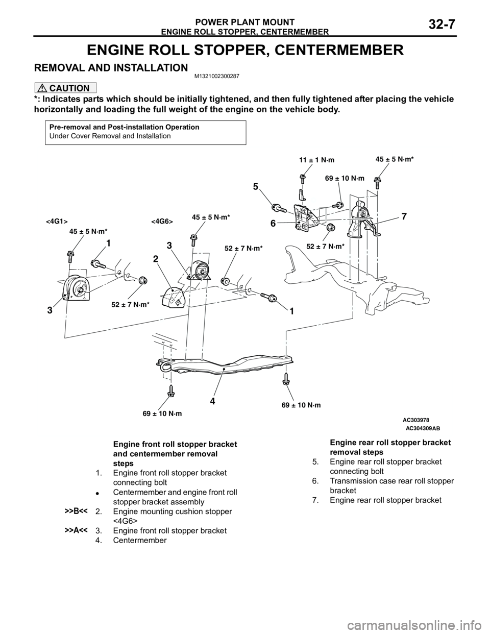
REMOVAL AND INSTALLATIONM1321002300287
CAUTION
*: Indicates parts which should be initially tightened, and then fully tightened after placing the vehicle
horizontally and loading the full weight of the engine on the vehicle body.
Pre-removal and Post-installation Operation
Under Cover Removal and Installation
AC303978
AC304309
45 ± 5 N·m*45 ± 5 N·m*
<4G1> <4G6>
52 ± 7 N·m*52 ± 7 N·m*
45 ± 5 N·m*
52 ± 7 N·m*
11 ± 1 N·m
69 ± 10 N·m
69 ± 10 N·m69 ± 10 N·m
1
32
1 3
4
5
67
AB
Engine front roll stopper bracket
and centermember removal
steps
1. Engine front roll stopper bracket
connecting bolt
•Centermember and engine front roll
stopper bracket assembly
>>B<<2. Engine mounting cushion stopper
<4G6>
>>A<<3. Engine front roll stopper bracket
4. CentermemberEngine rear roll stopper bracket
removal steps
5. Engine rear roll stopper bracket
connecting bolt
6. Transmission case rear roll stopper
bracket
7. Engine rear roll stopper bracket