Page 126 of 364

194G6 – ROCKER ARM / CAMSHAFT
Installation Service Point
Installation of OCV filter
Note :
Before fitting the filter, check that it is clean and is not damaged
or deformed in any way.
Installation of eye bolt
Note :
The oil pump may be damaged if the oil pipe joint turns with the
eye bolt when it is fitted.
Hold the oil pipe joint in place with a spanner, etc., and then tighten
the eye bolt to the specified torque 42 ±2 N-m.
Installation of cam position sensor
support
1. Wipe away all traces of the old liquid gasket left on the cam
position sensor support and the cylinder head.
2. Apply a 3 mm-thick coat of the liquid gasket to the parts of the
cam position sensor support indicated on the diagram.
Liquid Gasket
Product name : MZ100191 or equivalent
Installation of cam position sensing
cylinder
1. Set the camshaft to the top dead centre for No.1.
2. Install the various vanes of the cam position sensing cylinder at
the positions indicated on the diagram.
Installation of cover / gasket
1. Before installing the cover and gasket, put the camshaft to the
No.1 top dead centre position, and check that the vanes of the
respective sensing cylinders are located in the positions shown in
the diagram.
Eye bolt
Hold with
spanner, etc.
Oil pipe joint
Exhaust sideIntake side
Exhaust side
Exhaust sideIntake side
Intake sideVane
Vane
Vane
Vane VaneVane
Vane Vane
Vane
(large) Vane
(large) Vane
(small)
Vane
(small)
�A�*
�B� �*
�C�
�*
�D�
�*
�E�
�*
Page 130 of 364

234G6 - PISTONS / CONNECTING RODS
Installation Service Point
Installation of bearings on connecting rod
1. When replacing a bearing, connecting rod or crankshaft,
choose a bearing of the correct size which corresponds to the
external diameter of the crankshaft pin, in accordance with the
identification marks on the crankshaft pin and the connecting
rod bearing given in the table below.
2. The crankshaft identifier is engraved in the position shown in
the diagram.
3. The bearing identifier is engraved or printed at the position
shown in the diagram.
(Selecting a bearing : Example)
If the crankshaft identification mark is I, then choose a bearing
with the identification mark 0.
If it is difficult to make out the crankshaft identifier, measure the
external diameter of the pin and then choose the bearing that
corresponds to that diameter.
4. The selected bearing should be installed in the larger end of
the connecting rod and the cap.
�A�*
Crankshaft pin Connecting rod
bearing
Identification mark External diameter of
pin (mm)Identification mark
I44.995 – 45.005 0
II 44.985 – 44.995 1
III 44.980 – 44.985 2
Position of crankshaft pin diameter identification marks
Page 133 of 364

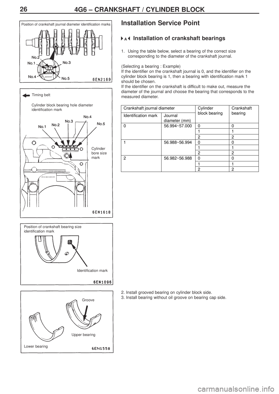
264G6 – CRANKSHAFT / CYLINDER BLOCK
Installation Service Point
Installation of crankshaft bearings
1. Using the table below, select a bearing of the correct size
corresponding to the diameter of the crankshaft journal.
(Selecting a bearing : Example)
If the identifier on the crankshaft journal is 0, and the identifier on the
cylinder block bearing is 1, then a bearing with identification mark 1
should be chosen.
If the identifier on the crankshaft is difficult to make out, measure the
diameter of the journal and choose the bearing that corresponds to the
measured diameter.
Crankshaft journal diameter
Identification mark Journal
diameter (mm)Cylinder
block bearingCrankshaft
bearing
00
11
056.994~57.000
22
00
11
156.988~56.994
22
00
11
256.982~56.988
22
2. Install grooved bearing on cylinder block side.
3. Install bearing without oil groove on bearing cap side.
Position of crankshaft journal diameter identification marks
Timing belt
Cylinder block bearing hole diameter
identification mark
Cylinder
bore size
mark
Position of crankshaft bearing size
identification mark
Identification mark
Groove
Lower bearingUpper bearing
�A�*
Page 136 of 364
Service Manual
Electrical Wiring Diagrams
Page 138 of 364

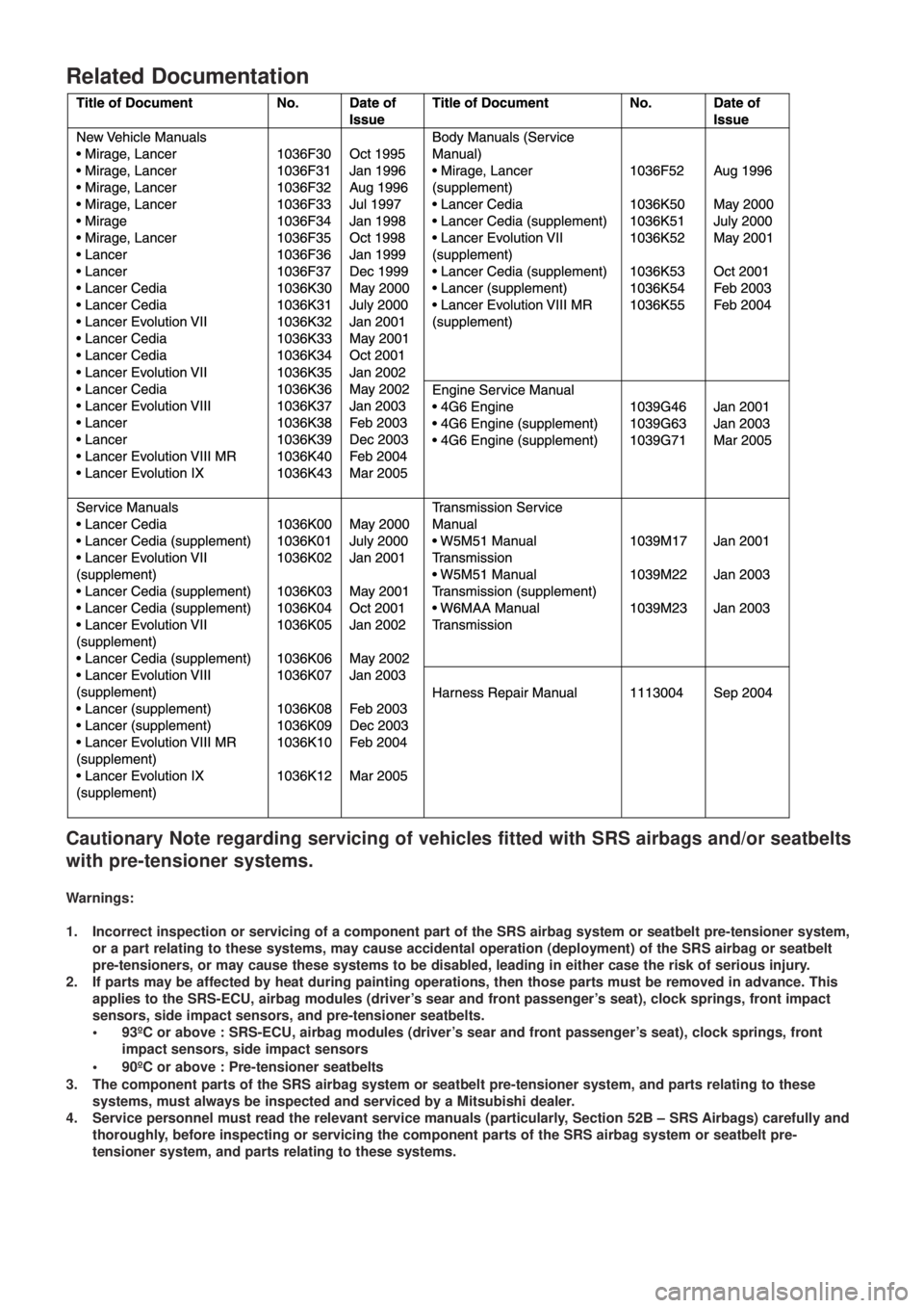
Related Documentation
Cautionary Note regarding servicing of vehicles fitted with SRS airbags and/or seatbelts
with pre-tensioner systems.
Warnings:
1. Incorrect inspection or servicing of a component part of the SRS airbag system or seatbelt pre-tensioner system,
or a part relating to these systems, may cause accidental operation (deployment) of the SRS airbag or seatbelt
pre-tensioners, or may cause these systems to be disabled, leading in either case the risk of serious injury.
2. If parts may be affected by heat during painting operations, then those parts must be removed in advance. This
applies to the SRS-ECU, airbag modules (driver’s sear and front passenger’s seat), clock springs, front impact
sensors, side impact sensors, and pre-tensioner seatbelts.
• 93ºC or above : SRS-ECU, airbag modules (driver’s sear and front passenger’s seat), clock springs, front
impact sensors, side impact sensors
•90ºC or above : Pre-tensioner seatbelts
3. The component parts of the SRS airbag system or seatbelt pre-tensioner system, and parts relating to these
systems, must always be inspected and serviced by a Mitsubishi dealer.
4. Service personnel must read the relevant service manuals (particularly, Section 52B – SRS Airbags) carefully and
thoroughly, before inspecting or servicing the component parts of the SRS airbag system or seatbelt pre-
tensioner system, and parts relating to these systems.
Page:
< prev 1-8 9-16 17-24