2005 MITSUBISHI 380 warning
[x] Cancel search: warningPage 1141 of 1500
KEYLESS ENTRY SYSTEM
BODY42-74
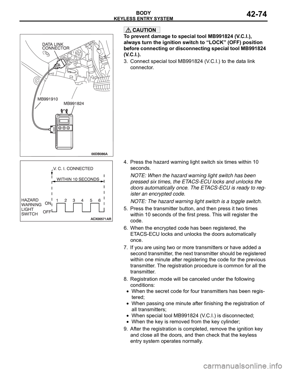
To prevent damage to special tool MB991824 (V.C.I.),
always turn the ignition switch to “LOCK” (OFF) position
before connecting or disconnecting special tool MB991824
(V.C.I.).
3. Connect special tool MB991824 (V.C.I.) to the data link
connector.
4. Press the hazard warning light switch six times within 10
seconds.
NOTE: When the hazard warning light switch has been
pressed six times, the ETACS-ECU locks and unlocks the
doors automatically once. The ETACS-ECU is ready to reg-
ister an encrypted code.
NOTE: The hazard warning light switch is a toggle switch.
5. Press the transmitter button, and then press it two times
within 10 seconds of the first press. This will register the
code.
6. When the encrypted code has been registered, the
ETACS-ECU locks and unlocks the doors automatically
once.
7. If you are using two or more transmitters or have added a
second transmitter, the next transmitter should be registered
within one minute after registering the code for the previous
transmitter. The registration procedure is common for all the
transmitter.
8. Registration mode will be canceled under the following
conditions:
When the secret code for four transmitters has been regis-
tered;
When passing one minute after finishing the registration of
all transmitters;
When special tool MB991824 (V.C.I.) is disconnected;
When the key is removed from the key cylinder;
9. After the registration is completed, remove the ignition key
and close all the doors, and then check that the keyless
entry system operates normally.
Page 1224 of 1500

HOW TO USE THIS MANUAL
GENERAL00-3
HOW TO USE THIS MANUALM1001000100897
MAINTENANCE, REPAIR AND
SERVICING EXPLANATIONS
This manual provides explanations, etc. concerning
procedures for the inspection, maintenance, repair
and servicing of the subject model. Unless otherwise
specified, each service procedure covers all models.
Procedures covering specific models are identified
by the model codes, or similar designation (engine
type, transaxle type, etc). A description of these des-
ignations is covered in this manual under "VEHICLE
IDENTIFICATION."
.
ON-VEHICLE SERVICE
The "ON-VEHICLE SERVICE" section has proce-
dures for performing inspections and adjustments of
particularly important components. These proce-
dures are done with regard to maintenance and ser-
vicing, but other inspections (looseness, play,
cracking, damage, etc.) must also be performed.
.
SERVICE PROCEDURES
The service steps are arranged in numerical order.
Attention to be paid in performing vehicle service are
described in detail in SERVICE POINTS.
DEFINITION OF TERMS
.
STANDARD VALUE
Indicates the value used as the standard for judging
whether or not a part or adjustment is correct.
.
LIMIT
Shows the maximum or minimum value for judging
whether or not a part or adjustment is acceptable.
.
REFERENCE VALUE
Indicates the adjustment value prior to starting the
work (presented in order to facilitate assembly and
adjustment procedures, and so they can be com-
pleted in a shorter time).
.
DANGER, WARNING, AND CAUTION
DANGER, WARNING, and CAUTION call special
attention to a necessary action or to an action that
must be avoided. The differences among DANGER,
WARNING, and CAUTION are as follows:
If a DANGER is not followed, the result is severe
bodily harm or even death.
If a WARNING is not followed, the result could be
bodily injury.
If a CAUTION is not followed, the result could be
damage to the vehicle, vehicle components or
service equipment.
TIGHTENING TORQUE INDICATION
The tightening torque indicates a median and its tol-
erance by a unit of N
m (in-lb.) or Nm (ft.-lb.). For
fasteners with no assigned torque value, refer to
P.00-32.
SPECIAL TOOL NOTE
Only MMC special tool part numbers are called out in
the repair sections of this manual. Please refer to the
special tool cross-reference chart located at the
beginning of each group, for the special tool number
that is available in your market.
ABBREVIATIONS
The following abbreviations are used in this manual
for classification of model types:
A/T:Automatic transaxle, or models equipped with
automatic transaxle.
MPI: Multipoint fuel injection, or engines equipped
with multiport fuel injection.
A/C: Air conditioning.
3.8L engine: 3.8 litre <6G75> engine, or a model
equipped with such an engine.
ABS: Anti-lock Braking System
TCL: Traction Control System
ECU: Electronic Control Unit
V.C.I.: Vehicle Communication Interface
SWS: Simplified Wiring System
CAN: Controller Area Network
M/T: Manual Transmission
SRS: Supplemental Restraint System
Page 1233 of 1500
HOW TO USE TROUBLESHOOTING/INSPECTION SERVICE POINTS
GENERAL00-12
IF INSPECTING WITH THE CONNECTOR
DISCONNECTED
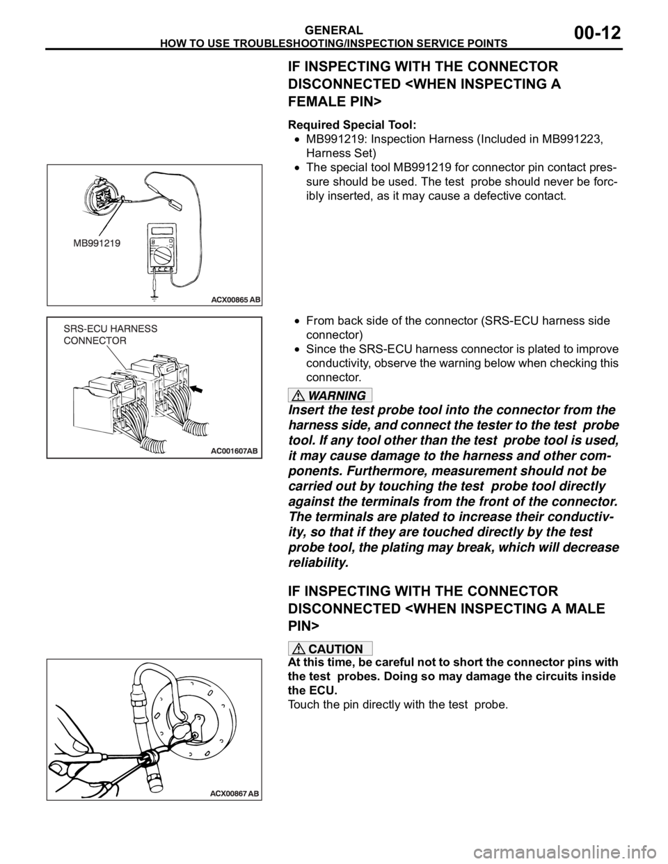
Required Special Tool:
MB991219: Inspection Harness (Included in MB991223,
Harness Set)
The special tool MB991219 for connector pin contact pres-
sure should be used. The test probe should never be forc-
ibly inserted, as it may cause a defective contact.
From back side of the connector (SRS-ECU harness side
connector)
Since the SRS-ECU harness connector is plated to improve
conductivity, observe the warning below when checking this
connector.
Insert the test probe tool into the connector from the
harness side, and connect the tester to the test probe
tool. If any tool other than the test probe tool is used,
it may cause damage to the harness and other com-
ponents. Furthermore, measurement should not be
carried out by touching the test probe tool directly
against the terminals from the front of the connector.
The terminals are plated to increase their conductiv-
ity, so that if they are touched directly by the test
probe tool, the plating may break, which will decrease
reliability.
IF INSPECTING WITH THE CONNECTOR
DISCONNECTED
At this time, be careful not to short the connector pins with
the test probes. Doing so may damage the circuits inside
the ECU.
Touch the pin directly with the test probe.
Page 1243 of 1500
PRECAUTIONS BEFORE SERVICE
GENERAL00-22
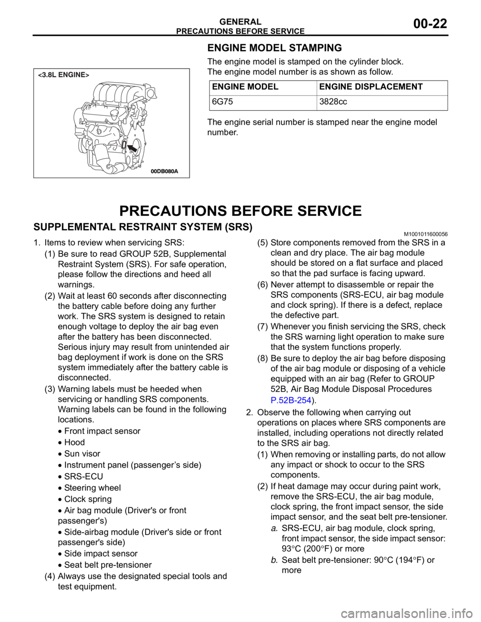
ENGINE MODEL STAMPING
The engine model is stamped on the cylinder block.
The engine model number is as shown as follow.
The engine serial number is stamped near the engine model
number.
PRECAUTIONS BEFORE SERVICE
SUPPLEMENTAL RESTRAINT SYSTEM (SRS)M1001011600056
1. Items to review when servicing SRS:
(1) Be sure to read GROUP 52B, Supplemental
Restraint System (SRS). For safe operation,
please follow the directions and heed all
warnings.
(2) Wait at least 60 seconds after disconnecting
the battery cable before doing any further
work. The SRS system is designed to retain
enough voltage to deploy the air bag even
after the battery has been disconnected.
Serious injury may result from unintended air
bag deployment if work is done on the SRS
system immediately after the battery cable is
disconnected.
(3) Warning labels must be heeded when
servicing or handling SRS components.
Warning labels can be found in the following
locations.
Front impact sensor
Hood
Sun visor
Instrument panel (passenger ’s side)
SRS-ECU
Steering wheel
Clock spring
Air bag module (Driver's or front
passenger's)
Side-airbag module (Driver's side or front
passenger's side)
Side impact sensor
Seat belt pre-tensioner
(4) Always use the designated special tools and
test equipment.(5) Store components removed from the SRS in a
clean and dry place. The air bag module
should be stored on a flat surface and placed
so that the pad surface is facing upward.
(6) Never attempt to disassemble or repair the
SRS components (SRS-ECU, air bag module
and clock spring). If there is a defect, replace
the defective part.
(7) Whenever you finish servicing the SRS, check
the SRS warning light operation to make sure
that the system functions properly.
(8) Be sure to deploy the air bag before disposing
of the air bag module or disposing of a vehicle
equipped with an air bag (Refer to GROUP
52B, Air Bag Module Disposal Procedures
P.52B-254).
2. Observe the following when carrying out
operations on places where SRS components are
installed, including operations not directly related
to the SRS air bag.
(1) When removing or installing parts, do not allow
any impact or shock to occur to the SRS
components.
(2) If heat damage may occur during paint work,
remove the SRS-ECU, the air bag module,
clock spring, the front impact sensor, the side
impact sensor, and the seat belt pre-tensioner.
a.SRS-ECU, air bag module, clock spring,
front impact sensor, the side impact sensor:
93
C (200F) or more
b.Seat belt pre-tensioner: 90
C (194F) or
more ENGINE MODEL ENGINE DISPLACEMENT
6G75 3828cc
Page 1272 of 1500
MAINTENANCE SERVICE
GENERAL00-51
18. SUSPENSION SYSTEM (INSPECT FOR
LOOSENESS AND DAMAGE)
M1001009600048
Visually inspect the front/rear suspension components for dete-
rioration and damage. Re-tighten the front/rear suspension
components retaining bolts to specified torque.
19. SRS AIR BAG (INSPECT FOR SRS SYSTEM)M1001003700326
The entire SRS including air bag and pre-tensioner seat belt
must be inspected by an authorized MITSUBISHI MOTORS
dealer 10 years.
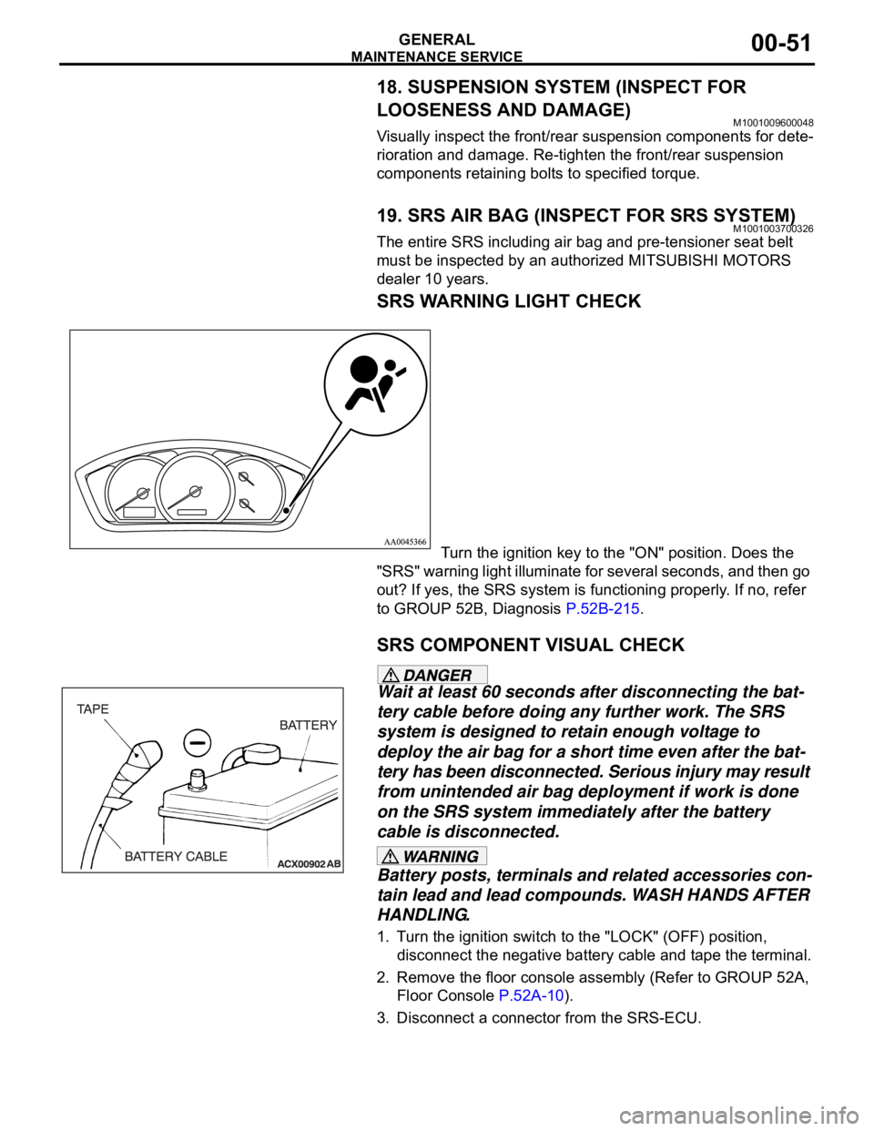
SRS WARNING LIGHT CHECK
Turn the ignition key to the "ON" position. Does the
"SRS" warning light illuminate for several seconds, and then go
out? If yes, the SRS system is functioning properly. If no, refer
to GROUP 52B, Diagnosis P.52B-215.
SRS COMPONENT VISUAL CHECK
Wait at least 60 seconds after disconnecting the bat-
tery cable before doing any further work. The SRS
system is designed to retain enough voltage to
deploy the air bag for a short time even after the bat-
tery has been disconnected. Serious injury may result
from unintended air bag deployment if work is done
on the SRS system immediately after the battery
cable is disconnected.
Battery posts, terminals and related accessories con-
tain lead and lead compounds. WASH HANDS AFTER
HANDLING.
1. Turn the ignition switch to the "LOCK" (OFF) position,
disconnect the negative battery cable and tape the terminal.
2. Remove the floor console assembly (Refer to GROUP 52A,
Floor Console P.52A-10).
3. Disconnect a connector from the SRS-ECU.
Page 1281 of 1500
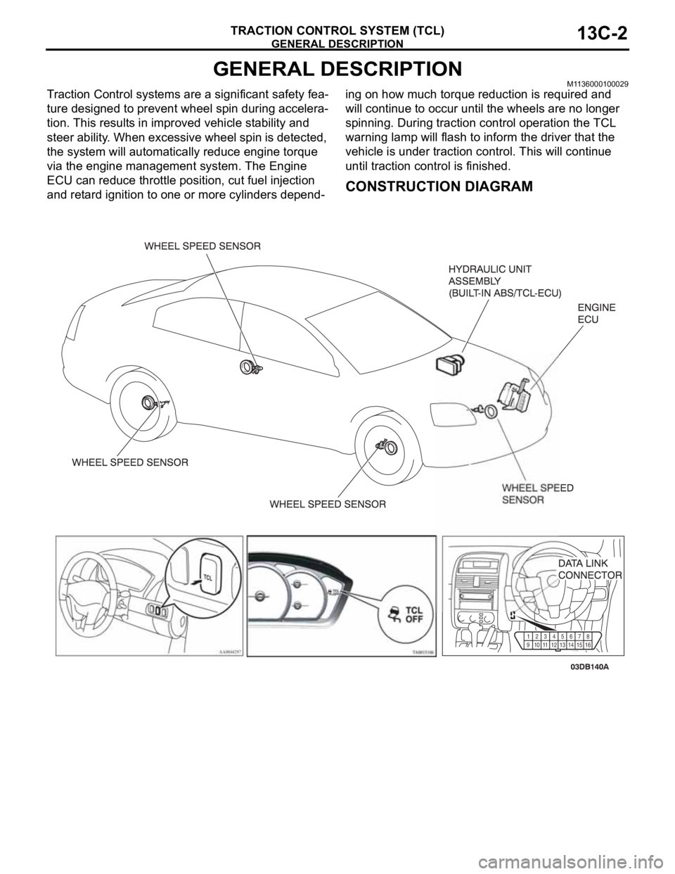
GENERAL DESCRIPTION
TRACTION CONTROL SYSTEM (TCL)13C-2
GENERAL DESCRIPTIONM1136000100029
Traction Control systems are a significant safety fea-
ture designed to prevent wheel spin during accelera-
tion. This results in improved vehicle stability and
steer ability. When excessive wheel spin is detected,
the system will automatically reduce engine torque
via the engine management system. The Engine
ECU can reduce throttle position, cut fuel injection
and retard ignition to one or more cylinders depend-ing on how much torque reduction is required and
will continue to occur until the wheels are no longer
spinning. During traction control operation the TCL
warning lamp will flash to inform the driver that the
vehicle is under traction control. This will continue
until traction control is finished.
CONSTRUCTION DIAGRAM
91011
1213141516 12345
678
Page 1460 of 1500
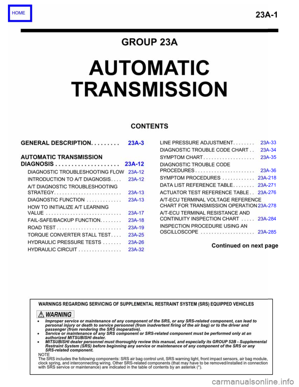
23A-1
GROUP 23A
AUTOMATIC
TRANSMISSION
CONTENTS
GENERAL DESCRIPTION. . . . . . . . .23A-3
AUTOMATIC TRANSMISSION
DIAGNOSIS . . . . . . . . . . . . . . . . . . . .23A-12
DIAGNOSTIC TROUBLESHOOTING FLOW23A-12
INTRODUCTION TO A/T DIAGNOSIS . . . . 23A-12
A/T DIAGNOSTIC TROUBLESHOOTING
STRATEGY . . . . . . . . . . . . . . . . . . . . . . . . . 23A-13
DIAGNOSTIC FUNCTION . . . . . . . . . . . . . 23A-13
HOW TO INITIALIZE A/T LEARNING
VALUE . . . . . . . . . . . . . . . . . . . . . . . . . . . . 23A-17
FAIL-SAFE/BACKUP FUNCTION. . . . . . . . 23A-18
ROAD TEST . . . . . . . . . . . . . . . . . . . . . . . . 23A-19
TORQUE CONVERTER STALL TEST . . . . 23A-25
HYDRAULIC PRESSURE TESTS . . . . . . . 23A-26
HYDRAULIC CIRCUIT . . . . . . . . . . . . . . . . 23A-32LINE PRESSURE ADJUSTMENT . . . . . . . . 23A-33
DIAGNOSTIC TROUBLE CODE CHART . . 23A-34
SYMPTOM CHART . . . . . . . . . . . . . . . . . . . 23A-35
DIAGNOSTIC TROUBLE CODE
PROCEDURES . . . . . . . . . . . . . . . . . . . . . . 23A-36
SYMPTOM PROCEDURES . . . . . . . . . . . . 23A-218
DATA LIST REFERENCE TABLE . . . . . . . . 23A-271
ACTUATOR TEST REFERENCE TABLE . . 23A-276
A/T-ECU TERMINAL VOLTAGE REFERENCE
CHART FOR TRANSMISSION OPERATION23A-278
A/T-ECU TERMINAL RESISTANCE AND
CONTINUITY INSPECTION CHART . . . . . 23A-284
INSPECTION PROCEDURE USING AN
OSCILLOSCOPE . . . . . . . . . . . . . . . . . . . . 23A-285
Continued on next page
WARNINGS REGARDING SERVICING OF SUPPLEMENTAL RESTRAINT SYSTEM (SRS) EQUIPPED VEHICLES
Page 1472 of 1500
AUTOMATIC TRANSMISSION DIAGNOSIS
AUTOMATIC TRANSMISSION23A-13
A/T DIAGNOSTIC TROUBLESHOOTING STRATEGYM1231007600339
Use these steps to plan your diagnostic strategy. If
you follow them carefully, you will find most A/T mal-
functions.
1. Gather as much information as possible about the
complaint from the customer.
2. Verify that the condition described by the
customer exists.
3. Check the vehicle for any A/T Diagnostic Trouble
Codes (DTCs).
4. If you can not verify the condition and there are no
DTCs, the malfunction is intermittent. For
information on how to cope with intermittent
malfunctions, refer to GROUP 00, How to Use
Troubleshooting/Inspection Service Points
How
to Cope with Intermittent Malfunction P.00-14.
5. If you can verify the condition but there are no
DTCs, or the system can not communicate with
diagnostic tool, refer to the Symptom Chart
P.23A-35.6. If there is a DTC, record the number of the code,
then erase the code from memory using
diagnostic tool.
7. Reconfirm the symptom with a Road Test.
8. If a DTC is set again, go to the Inspection Chart
for Diagnostic Trouble Codes.
9. If a DTC is not set again, the malfunction is
intermittent. For information on how to cope with
intermittent malfunctions, refer to GROUP 00,
How to Use Troubleshooting/Inspection Service
Points
How to Cope with Intermittent
Malfunction P.00-14.
10.After repairs are completed, conduct a Road Test
duplicating the complaint conditions to confirm the
malfunction has been eliminated.
DIAGNOSTIC FUNCTIONM1231022500135
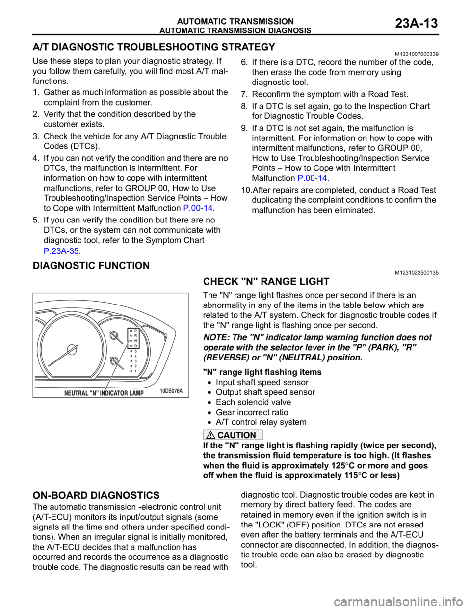
CHECK "N" RANGE LIGHT
The "N" range light flashes once per second if there is an
abnormality in any of the items in the table below which are
related to the A/T system. Check for diagnostic trouble codes if
the "N" range light is flashing once per second.
NOTE: The "N" indicator lamp warning function does not
operate with the selector lever in the "P" (PARK), "R"
(REVERSE) or "N" (NEUTRAL) position.
"N" range light flashing items
Input shaft speed sensor
Output shaft speed sensor
Each solenoid valve
Gear incorrect ratio
A/T control relay system
If the "N" range light is flashing rapidly (twice per second),
the transmission fluid temperature is too high. (It flashes
when the fluid is approximately 125
C or more and goes
off when the fluid is approximately 115
C or less)
ON-BOARD DIAGNOSTICS
The automatic transmission -electronic control unit
(A/T-ECU) monitors its input/output signals (some
signals all the time and others under specified condi-
tions). When an irregular signal is initially monitored,
the A/T-ECU decides that a malfunction has
occurred and records the occurrence as a diagnostic
trouble code. The diagnostic results can be read with diagnostic tool. Diagnostic trouble codes are kept in
memory by direct battery feed. The codes are
retained in memory even if the ignition switch is in
the "LOCK" (OFF) position. DTCs are not erased
even after the battery terminals and the A/T-ECU
connector are disconnected. In addition, the diagnos-
tic trouble code can also be erased by diagnostic
tool.