Page 1266 of 1500

MAINTENANCE SERVICE
GENERAL00-45
Engine Oil Filter Selection
This vehicle is equipped with a full-flow, throw-away oil filter.
The same type of filter is recommended as a replacement filter
for this vehicle. It is possible, particularly in cold weather, that
this vehicle may develop high oil pressure for a short duration.
Make sure that any replacement filter used on this vehicle is a
high-quality filter. The filter must withstand a pressure of 1,800
kPa (261 psi) [manufacturer's specifications] to avoid filter and
ultimately engine damage. The Genuine Mitsubishi high-quality
filter and is strongly recommended for use on this vehicle.
Any replacement oil filter should be installed in accordance with
the oil filter manufacturer's installation instructions.
.
Oil Filter Replacement
Use care as oil could be hot.
1. Drain the engine oil by removing the oil drain plug.
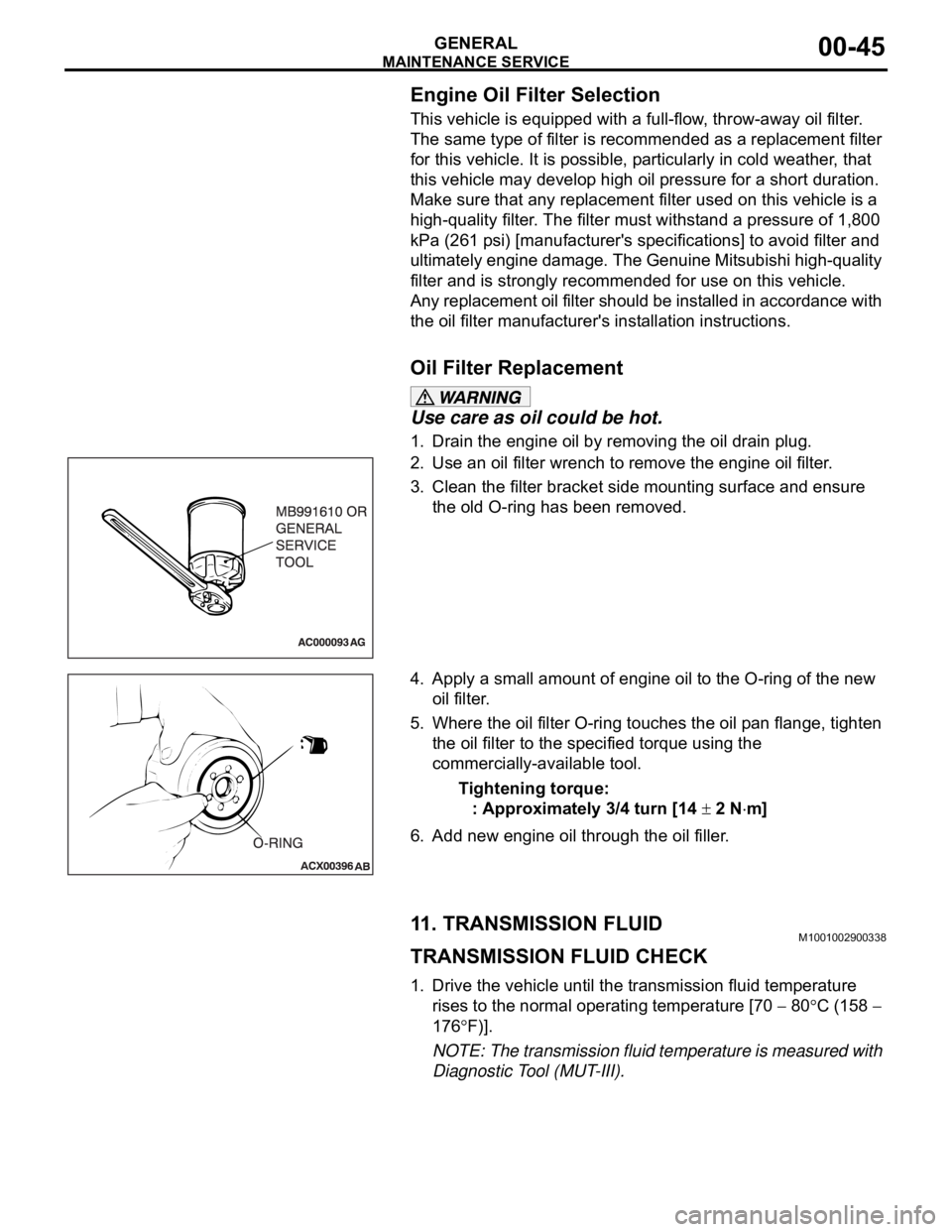
2. Use an oil filter wrench to remove the engine oil filter.
3. Clean the filter bracket side mounting surface and ensure
the old O-ring has been removed.
4. Apply a small amount of engine oil to the O-ring of the new
oil filter.
5. Where the oil filter O-ring touches the oil pan flange, tighten
the oil filter to the specified torque using the
commercially-available tool.
Tightening torque:
: Approximately 3/4 turn [14
2 Nm]
6. Add new engine oil through the oil filler.
11. TRANSMISSION FLUIDM1001002900338
TRANSMISSION FLUID CHECK
1. Drive the vehicle until the transmission fluid temperature
rises to the normal operating temperature [70
80C (158
176
F)].
NOTE: The transmission fluid temperature is measured with
Diagnostic Tool (MUT-III).
Page 1268 of 1500

MAINTENANCE SERVICE
GENERAL00-47
6. Securely insert the dipstick.
NOTE: The transmission fluid should always be replaced
under the following conditions:
.
When troubleshooting the transaxle.
When overhauling the transaxle.
When the transmission fluid is noticeably dirty or burnt
(driving under severe conditions).
TRANSMISSION FLUID CHANGE
Refer to GROUP 23A, Automatic Transmission - On-vehicle
Service P.23A-296.
12. ENGINE COOLANT (CHANGE)M1001003100357
Check the cooling system parts such as the radiator, heater
and oil cooler hoses, thermostat and their connections for leak-
age and damage.
.
CHANGING COOLANT
1. Set the temperature control knob to the "HOT" position.
2. Run the engine until the engine coolant warms, and then
stop the engine.
When removing the radiator cap, use care to avoid
contact with hot coolant or steam. Place a shop towel
over the cap and turn the cap counterclockwise a lit-
tle to let the pressure escape through the vinyl tube.
After relieving the steam pressure, remove the cap by
slowly turning it counterclockwise.
3. Drain the water from the radiator, heater core and engine
after unplugging the radiator drain plug and removing the
radiator cap.
Page 1407 of 1500

EMISSION CONTROL
ENGINE AND EMISSION CONTROL17-76
EMISSION CONTROL
GENERAL DESCRIPTIONM1173000100314
The emission control system consists of the fol-
lowing subsystems:
Positive crankcase ventilation system
Evaporative emission system
Exhaust emission control system
DIAGNOSISM1173000700112
SPECIAL TOOLSM1173000600193
SYMPTOM PROBABLE CAUSE REMEDY
Engine will not start or hard
to startVacuum hose disconnected or damaged Repair or replace
Malfunction of the evaporative emission
purge solenoidRepair or replace
Rough idle or engine stalls
Vacuum hose disconnected or damaged. Repair or replace
Malfunction of the positive crankcase
ventilation valveReplace
Malfunction of the purge control system Check the system; If there is a
problem, check its component
parts.
Excessive oil consumption Positive crankcase ventilation line
cloggedCheck positive crankcase
ventilation system
TOOL TOOL NUMBER AND
NAMESUPERSESSION APPLICATION
MB995061
Purge flow indicatorMLR6890A
Part of MIT280220Inspection of purge
control system
MD998770
Oxygen sensor wrenchMD998770-01 or General
service toolRemoval/installation of
heated oxygen sensor
Page 1416 of 1500
SPECIFICATIONS
ENGINE AND EMISSION CONTROL17-85
SPECIFICATIONS
FASTENER TIGHTENING SPECIFICATIONSM1173006400324
SERVICE SPECIFICATIONSM1173000300545
ITEM SPECIFICATION
Auto-cruise control system
Lower cover cap bolt 9.0
2.0 Nm (80 17 in-lb)
Steering wheel assembly nut 41
8 Nm (30 6 ft-lb)
Engine control system
Accelerator pedal assembly nut 13
2 Nm ( 111 22 in-lb)
ITEMSSTANDARD VALUE
Engine control system
Curb idle speed r/min 3.8L Engine 680
100
Emission control system
Purge flow cm
3/s (SCFH) [at 80 95C (176 205F) with sudden revving]20 (2.5)
Evaporative emission purge solenoid coil resistance [at 20
C)] 16
Page 1486 of 1500
![MITSUBISHI 380 2005 Workshop Manual AUTOMATIC TRANSMISSION DIAGNOSIS
AUTOMATIC TRANSMISSION23A-27
3. Connect the special tools (3.0 MPa (427 psi) oil pressure
gauge [MD998330] and adapters [MD998332, MD998900])
to each pressure discha MITSUBISHI 380 2005 Workshop Manual AUTOMATIC TRANSMISSION DIAGNOSIS
AUTOMATIC TRANSMISSION23A-27
3. Connect the special tools (3.0 MPa (427 psi) oil pressure
gauge [MD998330] and adapters [MD998332, MD998900])
to each pressure discha](/manual-img/19/57086/w960_57086-1485.png)
AUTOMATIC TRANSMISSION DIAGNOSIS
AUTOMATIC TRANSMISSION23A-27
3. Connect the special tools (3.0 MPa (427 psi) oil pressure
gauge [MD998330] and adapters [MD998332, MD998900])
to each pressure discharge port.
NOTE: .
2ND: Second brake pressure port
UD: Underdrive clutch pressure port
LR: Low-reverse brake pressure port
DR: Torque converter release pressure port
DA: Torque converter apply pressure port
RV: Reverse clutch pressure port
OD: Overdrive clutch pressure port
DIR: Direct clutch pressure port
RED: Reduction clutch pressure port
4. Restart the engine.
5. Check that there are no leaks around the special tool port
adapters.
6. Measure the hydraulic pressure at each port under the
conditions given in the standard hydraulic pressure table,
and check that the measured values are within the standard
value ranges.
7. If the pressure is not within the standard value, stop the
engine and refer to the hydraulic pressure test diagnosis
table.
8. Remove the O-ring from the port plug and replace it.
9. Remove the special tool, and install the plugs to the
hydraulic pressure ports.
10.Start the engine and check that there are no leaks around
the plugs.
Page 1487 of 1500

AUTOMATIC TRANSMISSION DIAGNOSIS
AUTOMATIC TRANSMISSION23A-28
STANDARD HYDRAULIC PRESSURE TABLE
NOTE: When the torque converter pressure is measured, the engine speed should be 1,500 r/min or less.
HYDRAULIC PRESSURE TEST DIAGNOSIS TABLE
MEASUREMENT
CONDITIONSSTANDARD HYDRAULIC PRESSURE kPa
SELECT-
OR
LEVER
POS’N SHIFT
RANGE
POSITIO
NENGINE
SPEED
(r/min)UNDERDRIVE
CLUTCH
PRESSURE
[UD]REVERSE
CLUTCH
PRESSURE
[RV]OVERDRIVE
CLUTCH
PRESSURE
[OD]DIRECT
CLUTCH
PRESSURE
[DIR]LOW-
REVERSE
BRAKE
PRESSURE
[LR]SECOND
BRAKE
PRESSURE
[2ND]TORQUE
CONVERTER
PRESSURE
[DR]
P2,500260 360260 360
R Rev. 2,500
12701770 12701770 500 730
N
2,500260 360 220 360
Spo rt
mode1st 2,500 980
1050 980 1050 500 730
2nd 2,500 980
1050 980 1050 500 730
3rd 2,500 780
900 780 900 450 720
4th 2,500 780
900 780 900 780 880 450 720
5th 2,500
780 900 780 880 780 880 450 720
SYMPTOM PROBABLE CAUSE
All hydraulic pressures are high. Malfunction of the regulator valve
All hydraulic pressures are low. Malfunction of the oil pump
Clogged internal oil filter
Clogged oil cooler
Malfunction of the regulator valve
Malfunction of the relief valve
Incorrect valve body installation
Improperly installed solenoid valves
Damaged solenoid valve O-rings
Hydraulic pressure is abnormal
in reverse gear only.Malfunction of the regulator valve
Clogged orifice
Incorrect valve body installation
Hydraulic pressure is abnormal
in 3rd or 4th gear only.Malfunction of the overdrive solenoid valve
Malfunction of the overdrive pressure control valve
Malfunction of the regulator valve
Malfunction of the switch valve
Clogged orifice
Incorrect valve body installation