Page 1243 of 1500

PRECAUTIONS BEFORE SERVICE
GENERAL00-22
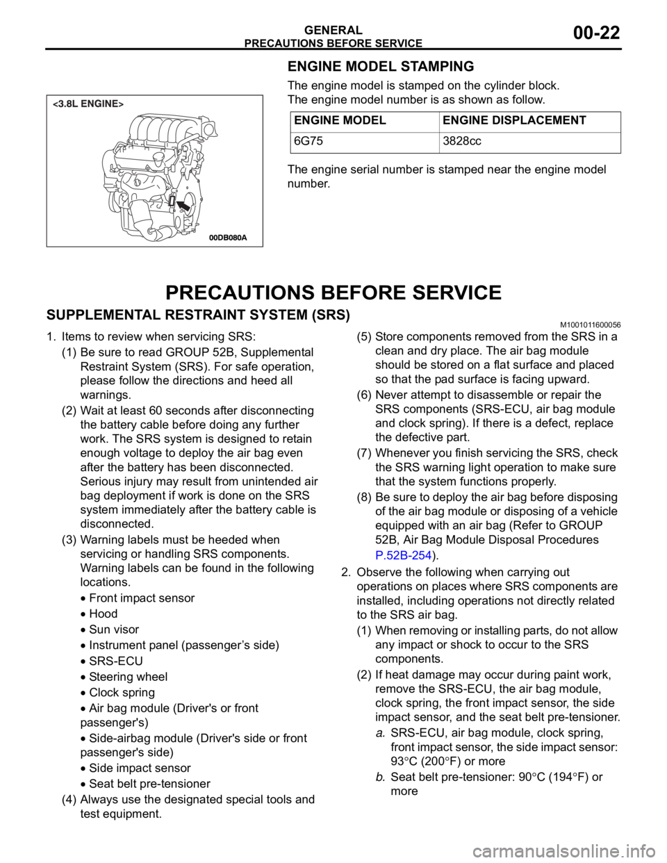
ENGINE MODEL STAMPING
The engine model is stamped on the cylinder block.
The engine model number is as shown as follow.
The engine serial number is stamped near the engine model
number.
PRECAUTIONS BEFORE SERVICE
SUPPLEMENTAL RESTRAINT SYSTEM (SRS)M1001011600056
1. Items to review when servicing SRS:
(1) Be sure to read GROUP 52B, Supplemental
Restraint System (SRS). For safe operation,
please follow the directions and heed all
warnings.
(2) Wait at least 60 seconds after disconnecting
the battery cable before doing any further
work. The SRS system is designed to retain
enough voltage to deploy the air bag even
after the battery has been disconnected.
Serious injury may result from unintended air
bag deployment if work is done on the SRS
system immediately after the battery cable is
disconnected.
(3) Warning labels must be heeded when
servicing or handling SRS components.
Warning labels can be found in the following
locations.
Front impact sensor
Hood
Sun visor
Instrument panel (passenger ’s side)
SRS-ECU
Steering wheel
Clock spring
Air bag module (Driver's or front
passenger's)
Side-airbag module (Driver's side or front
passenger's side)
Side impact sensor
Seat belt pre-tensioner
(4) Always use the designated special tools and
test equipment.(5) Store components removed from the SRS in a
clean and dry place. The air bag module
should be stored on a flat surface and placed
so that the pad surface is facing upward.
(6) Never attempt to disassemble or repair the
SRS components (SRS-ECU, air bag module
and clock spring). If there is a defect, replace
the defective part.
(7) Whenever you finish servicing the SRS, check
the SRS warning light operation to make sure
that the system functions properly.
(8) Be sure to deploy the air bag before disposing
of the air bag module or disposing of a vehicle
equipped with an air bag (Refer to GROUP
52B, Air Bag Module Disposal Procedures
P.52B-254).
2. Observe the following when carrying out
operations on places where SRS components are
installed, including operations not directly related
to the SRS air bag.
(1) When removing or installing parts, do not allow
any impact or shock to occur to the SRS
components.
(2) If heat damage may occur during paint work,
remove the SRS-ECU, the air bag module,
clock spring, the front impact sensor, the side
impact sensor, and the seat belt pre-tensioner.
a.SRS-ECU, air bag module, clock spring,
front impact sensor, the side impact sensor:
93
C (200F) or more
b.Seat belt pre-tensioner: 90
C (194F) or
more ENGINE MODEL ENGINE DISPLACEMENT
6G75 3828cc
Page 1272 of 1500

MAINTENANCE SERVICE
GENERAL00-51
18. SUSPENSION SYSTEM (INSPECT FOR
LOOSENESS AND DAMAGE)
M1001009600048
Visually inspect the front/rear suspension components for dete-
rioration and damage. Re-tighten the front/rear suspension
components retaining bolts to specified torque.
19. SRS AIR BAG (INSPECT FOR SRS SYSTEM)M1001003700326
The entire SRS including air bag and pre-tensioner seat belt
must be inspected by an authorized MITSUBISHI MOTORS
dealer 10 years.
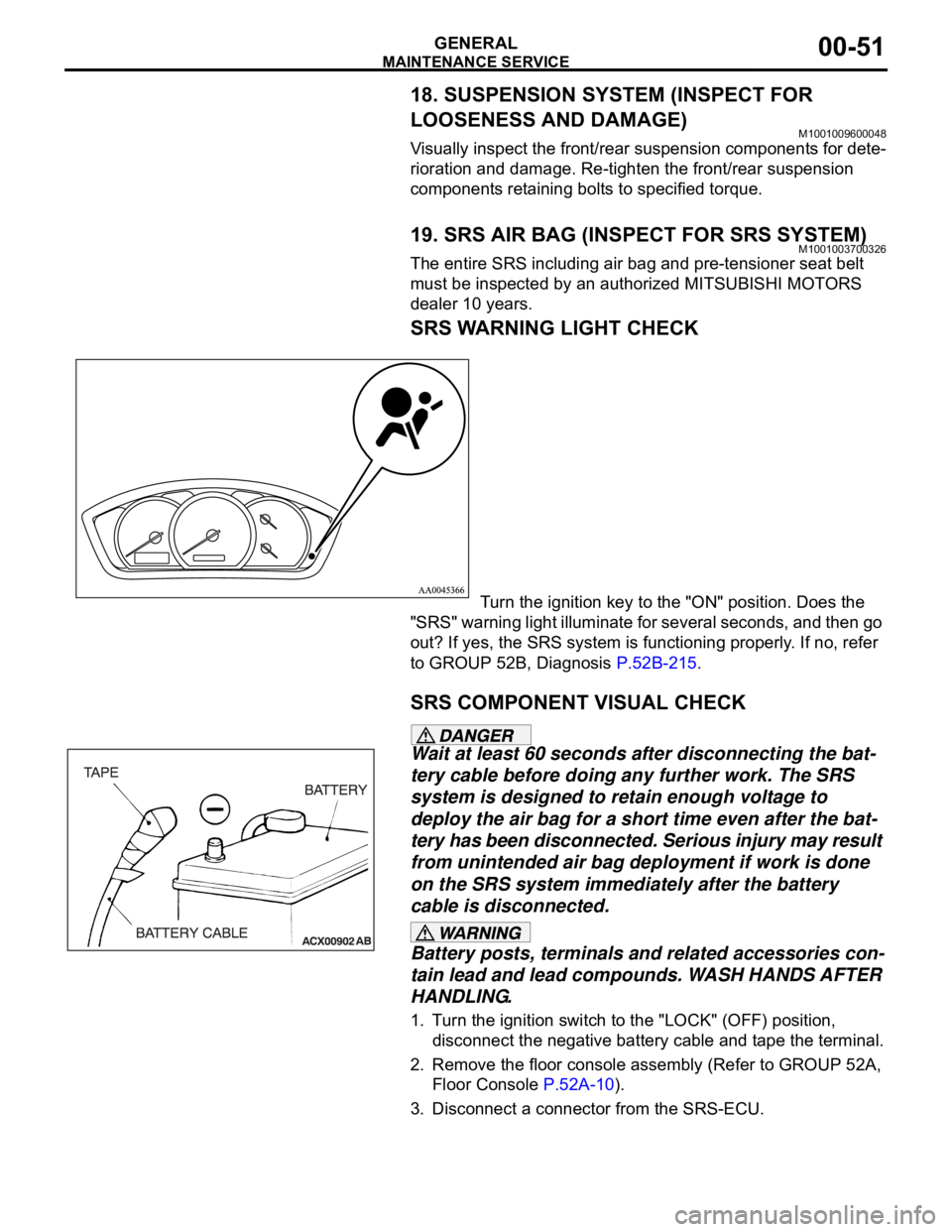
SRS WARNING LIGHT CHECK
Turn the ignition key to the "ON" position. Does the
"SRS" warning light illuminate for several seconds, and then go
out? If yes, the SRS system is functioning properly. If no, refer
to GROUP 52B, Diagnosis P.52B-215.
SRS COMPONENT VISUAL CHECK
Wait at least 60 seconds after disconnecting the bat-
tery cable before doing any further work. The SRS
system is designed to retain enough voltage to
deploy the air bag for a short time even after the bat-
tery has been disconnected. Serious injury may result
from unintended air bag deployment if work is done
on the SRS system immediately after the battery
cable is disconnected.
Battery posts, terminals and related accessories con-
tain lead and lead compounds. WASH HANDS AFTER
HANDLING.
1. Turn the ignition switch to the "LOCK" (OFF) position,
disconnect the negative battery cable and tape the terminal.
2. Remove the floor console assembly (Refer to GROUP 52A,
Floor Console P.52A-10).
3. Disconnect a connector from the SRS-ECU.
Page 1472 of 1500

AUTOMATIC TRANSMISSION DIAGNOSIS
AUTOMATIC TRANSMISSION23A-13
A/T DIAGNOSTIC TROUBLESHOOTING STRATEGYM1231007600339
Use these steps to plan your diagnostic strategy. If
you follow them carefully, you will find most A/T mal-
functions.
1. Gather as much information as possible about the
complaint from the customer.
2. Verify that the condition described by the
customer exists.
3. Check the vehicle for any A/T Diagnostic Trouble
Codes (DTCs).
4. If you can not verify the condition and there are no
DTCs, the malfunction is intermittent. For
information on how to cope with intermittent
malfunctions, refer to GROUP 00, How to Use
Troubleshooting/Inspection Service Points
How
to Cope with Intermittent Malfunction P.00-14.
5. If you can verify the condition but there are no
DTCs, or the system can not communicate with
diagnostic tool, refer to the Symptom Chart
P.23A-35.6. If there is a DTC, record the number of the code,
then erase the code from memory using
diagnostic tool.
7. Reconfirm the symptom with a Road Test.
8. If a DTC is set again, go to the Inspection Chart
for Diagnostic Trouble Codes.
9. If a DTC is not set again, the malfunction is
intermittent. For information on how to cope with
intermittent malfunctions, refer to GROUP 00,
How to Use Troubleshooting/Inspection Service
Points
How to Cope with Intermittent
Malfunction P.00-14.
10.After repairs are completed, conduct a Road Test
duplicating the complaint conditions to confirm the
malfunction has been eliminated.
DIAGNOSTIC FUNCTIONM1231022500135
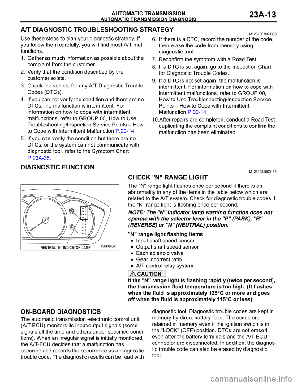
CHECK "N" RANGE LIGHT
The "N" range light flashes once per second if there is an
abnormality in any of the items in the table below which are
related to the A/T system. Check for diagnostic trouble codes if
the "N" range light is flashing once per second.
NOTE: The "N" indicator lamp warning function does not
operate with the selector lever in the "P" (PARK), "R"
(REVERSE) or "N" (NEUTRAL) position.
"N" range light flashing items
Input shaft speed sensor
Output shaft speed sensor
Each solenoid valve
Gear incorrect ratio
A/T control relay system
If the "N" range light is flashing rapidly (twice per second),
the transmission fluid temperature is too high. (It flashes
when the fluid is approximately 125
C or more and goes
off when the fluid is approximately 115
C or less)
ON-BOARD DIAGNOSTICS
The automatic transmission -electronic control unit
(A/T-ECU) monitors its input/output signals (some
signals all the time and others under specified condi-
tions). When an irregular signal is initially monitored,
the A/T-ECU decides that a malfunction has
occurred and records the occurrence as a diagnostic
trouble code. The diagnostic results can be read with diagnostic tool. Diagnostic trouble codes are kept in
memory by direct battery feed. The codes are
retained in memory even if the ignition switch is in
the "LOCK" (OFF) position. DTCs are not erased
even after the battery terminals and the A/T-ECU
connector are disconnected. In addition, the diagnos-
tic trouble code can also be erased by diagnostic
tool.
Page:
< prev 1-8 9-16 17-24