Page 877 of 1500
DUCTS
HEATER, AIR CONDITIONING AND VENTILATION55-176
DUCTS Cont.
. REAR CONSOLE DUCT
REMOVAL STEPS
6. REMOVE TRIM CLIP FROM
DUCT, CONSOLE A
7. REMOVE 2 TRIM CLIPS FROM
DUCT CONSOLE C8. REMOVE 3 SCREWS FROM
DUCT CONSOLE B
9. REMOVE 2 SCREWS FROM
DUCT CONSOLE D
10. TRIM CLIP . REAR CONSOLE DUCT
REMOVAL STEPS (Continued)
Page 1026 of 1500

CROSSMEMBER
POWER PLANT MOUNT32-9
CROSSMEMBER
REMOVAL AND INSTALLATIONM1321003200551
Before removing the steering wheel and air bag module assembly, always refer to GROUP 52B -
Service Precautions (P.52B-16), Air bag Module and Clock Spring (P.52B-237). Also, set the front
wheels so that they are facing straight forward, and remove the ignition key. If you fail to do this,
the SRS clock spring will be damaged, causing the SRS air bag to be inoperative and serious
injury.
*1: Indicates parts which should be initially tightened, and then fully tightened after placing the
vehicle horizontally and loading the full weight of the engine on the vehicle body.
*2: Indicates parts which should be temporarily tightened, and then fully tightened with the vehicle
on the ground in the unladen condition.
Pre-removal Operation
Power Steering Fluid Draining (Refer to GROUP 37,
On-vehicle Service Fluid Replacement P.37-18).
Power Steering Hoses Removal and Installation (Refer to
GROUP 37, Power Steering Hoses P.37A-57).
Air Bag Module and Steering Wheel Assembly Removal
(Refer to GROUP 37, Steering Wheel P.37-23).
Clock Spring Removal (Refer to GROUP 52B, Air Bag
Module and Clock Spring P.52B-237).
Floor Console Assembly Removal (Refer to GROUP 52A,
Floor Console Assembly P.52A-10).
Front Scuff Plate (LH) and Cowl Side Trim (LH) Removal
(Refer to GROUP 52A, Trims P.52A-11).
Trunk Lid Release Handle Cover Removal (Refer to
GROUP 42, Trunk Lid P.42-63).
Accelerator Stopper Removal (Refer to GROUP 17,
Accelerator Pedal P.17-9).
Front Floor Carpet Removal
Centremember Removal (Refer to P.32-7).Post-installation Operation
Centremember Installation (Refer to P.32-7).
Front Floor Carpet Installation
Accelerator Stopper Installation (Refer to GROUP 17,
Accelerator Pedal P.17-9).
Trunk Lid Release Handle Cover Installation (Refer to
GROUP 42, Trunk Lid P.42-63).
Front Scuff Plate (LH) and Cowl Side Trim (LH) Installa-
tion (Refer to GROUP 52A, Trims P.52A-11).
Floor Console Assembly Installation (Refer to GROUP
52A, Floor Console Assembly P.52A-10).
Clock Spring Installation (Refer to GROUP 52B, Air Bag
Module and Clock Spring P.52B-237).
Steering Wheel Assembly and Air Bag Module Installation
(Refer to P.37-23).
Check the dust cover for cracks or damage by pushing it
with your finger.
Power Steering Fluid Supplying (Refer to GROUP 37,
On-vehicle Service Fluid Replacement P.37-18).
Power Steering Fluid Line Bleeding (Refer to P.37-18).
Checking Steering Wheel Position with Wheels Straight
Ahead.
Front Wheel Alignment Adjustment (Refer to GROUP 33,
On-vehicle Service
Front Wheel Alignment Check and
Adjustment P.33-6).
Page 1147 of 1500

SUNROOF ASSEMBLY
BODY42-80
SUNROOF ASSEMBLY
REMOVAL AND INSTALLATIONM1426001200308
Post-installation Operation
Sunroof assembly>
Sunroof Water Test (Refer to P.42-75).
Sunroof Fit Adjustment (Refer to P.42-76).
Post-installation Operation
Sunroof motor assembly>
Sunroof Initializing Adjustment (Refer to P.42-77).
REMOVAL
1. ROOF LID GLASS ASSEMBLY
2. OVERHEAD CONSOLE ASSEMBLY
DRAIN PIPE REMOVAL STEPS
FRONT HEADLINING PAD (REFER
TO GROUP 52A, HEADLINING
P.52A-19).
FRONT SPLASH SHIELD (REFER
TO P.42-10).
UPPER FRAME TO FRONT PILLAR
BRACE (FRONT DRAIN PIPE )
(REFER TO P.42-84).
INSTRUMENT PANEL PARCEL BOX
(FRONT DRAIN PIPE )
(REFER TO GROUP 52A,
INSTRUMENT PANEL P.52A-4).
>>A<<3. FRONT DRAIN PIPE
REAR HEADLINING PAD (REFER
TO GROUP 52A, HEADLINING
P.52A-19).
TRUNK TRIM ASSEMBLY (REFER
TO GROUP 52A, TRIMS P.52A-11).
REAR SPLASH SHIELD (REFER TO
GROUP 51, REAR BUMPER P.51-5).
>>A<<4. REAR DRAIN PIPE
SUNROOF MOTOR ASSEMBLY
REMOVAL STEPS
HEADLINING (REFER TO GROUP
52A, HEADLINING P.52A-19).
5. SUNROOF MOTOR ASSEMBLYDRAIN PIPE REMOVAL STEPS
Page 1148 of 1500
SUNROOF ASSEMBLY
BODY42-81
Required Special Tool:
MB991223: Harness set
INSTALLATION SERVICE POINT
.
>>A<< REAR DRAIN PIPE/FRONT DRAIN PIPE
INSTALLATION
Install the grommet, and then position the drain pipe so that it
protrudes from the grommet as shown in the illustration.
SUNROOF ASSEMBLY REMOVAL
STEPS
1. ROOF LID GLASS ASSEMBLY
HEADLINING (REFER TO GROUP
52A, HEADLINING P.52A-19).
DRAIN PIPE CONNECTION
5. SUNROOF MOTOR ASSEMBLY6. OVERHEAD CONSOLE BRACKET
7. SUNROOF ASSEMBLY SUNROOF ASSEMBLY REMOVAL
STEPS (Continued)
Page 1211 of 1500

ON-VEHICLE SERVICE
PARKING BRAKES36-4
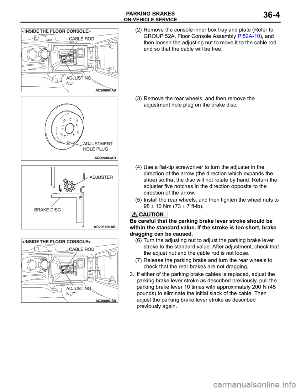
(2) Remove the console inner box tray and plate (Refer to
GROUP 52A, Floor Console Assembly P.52A-10), and
then loosen the adjusting nut to move it to the cable rod
end so that the cable will be free.
(3) Remove the rear wheels, and then remove the
adjustment hole plug on the brake disc.
(4) Use a flat-tip screwdriver to turn the adjuster in the
direction of the arrow (the direction which expands the
shoe) so that the disc will not rotate by hand. Return the
adjuster five notches in the direction opposite to the
direction of the arrow.
(5) Install the rear wheels, and then tighten the wheel nuts to
98
10 Nm (73 7 ft-lb).
Be careful that the parking brake lever stroke should be
within the standard value. If the stroke is too short, brake
dragging can be caused.
(6) Turn the adjusting nut to adjust the parking brake lever
stroke to the standard value. After adjustment, check that
the adjust nut and the cable rod is not loose.
(7) Release the parking brake and turn the rear wheels to
check that the rear brakes are not dragging.
3. If either of the parking brake cables is replaced, adjust the
parking brake lever stroke as described previously, pull the
parking brake lever 10 times with approximately 200 N (45
pounds) to eliminate the initial slack of the cable. Then
adjust the parking brake lever stroke as described
previously again.
Page 1212 of 1500

ON-VEHICLE SERVICE
PARKING BRAKES36-5
PARKING BRAKE SWITCH CHECKM1361003300411
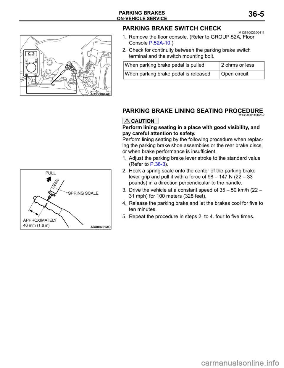
1. Remove the floor console. (Refer to GROUP 52A, Floor
Console P.52A-10.)
2. Check for continuity between the parking brake switch
terminal and the switch mounting bolt.
PARKING BRAKE LINING SEATING PROCEDUREM1361001100262
Perform lining seating in a place with good visibility, and
pay careful attention to safety.
Perform lining seating by the following procedure when replac-
ing the parking brake shoe assemblies or the rear brake discs,
or when brake performance is insufficient.
1. Adjust the parking brake lever stroke to the standard value
(Refer to P.36-3).
2. Hook a spring scale onto the center of the parking brake
lever grip and pull it with a force of 98
147 N (22 33
pounds) in a direction perpendicular to the handle.
3. Drive the vehicle at a constant speed of 35
50 km/h (22
31 mph) for 100 meters (328 feet).
4. Release the parking brake and let the brakes cool for five to
ten minutes.
5. Repeat the procedure in steps 2. to 4. four to five times.When parking brake pedal is pulled 2 ohms or less
When parking brake pedal is released Open circuit
Page 1213 of 1500
PARKING BRAKE LEVER
PARKING BRAKES36-6
PARKING BRAKE LEVER
REMOVAL AND INSTALLATIONM1361001300363
Pre-removal Operation
Rear Floor Console Assembly and Rear Console Bracket
Removal (Refer to GROUP 52A, Floor Console P.52A-10.)Post-installation Operation
Parking Brake Lever Stroke Adjustment (Refer to P.36-3.)
Rear Console Bracket and Rear Floor Console Assembly
Installation (Refer to GROUP 52A, Floor Console
P.52A-10.)
REMOVAL STEPS
1. ADJUSTING NUT
2. PARKING BRAKE SWITCH
CONNECTOR
3. PARKING BRAKE CABLE
CONNECTION
4. PARKING BRAKE LEVER
ASSEMBLY
5. PARKING BRAKE SWITCH
Page 1214 of 1500
PARKING BRAKE CABLE
PARKING BRAKES36-7
PARKING BRAKE CABLE
REMOVAL AND INSTALLATIONM1361001900547
Pre-removal Operation
Floor Console Assembly Removal (Refer to GROUP 52A,
Floor Console Assembly P.52A-10).Post-installation OperationFloor Console Assembly Installation (Refer to GROUP
52A, Floor Console Assembly P.52A-10).
Parking Brake Lever Stroke Check and Adjustment (Refer
to P.36-3).
REMOVAL STEPS
SHOE ASSEMBLY (REFER TO P.36-8).
REAR PARKING BRAKE CABLE TO
BAKING PLATE CONNECTION (REFER
TO P.36-8).
FRONT PARKING BRAKE CABLE TO
REAR PARKING BRAKE CABLE
CONNECTION (REFER TO P.36-6).
1. REAR PARKING BRAKE CABLE
2. O-RING