2005 MITSUBISHI 380 clock
[x] Cancel search: clockPage 1129 of 1500
TRUNK LID
BODY42-62
TRUNK LID HEIGHT ADJUSTMENTM1421008300044
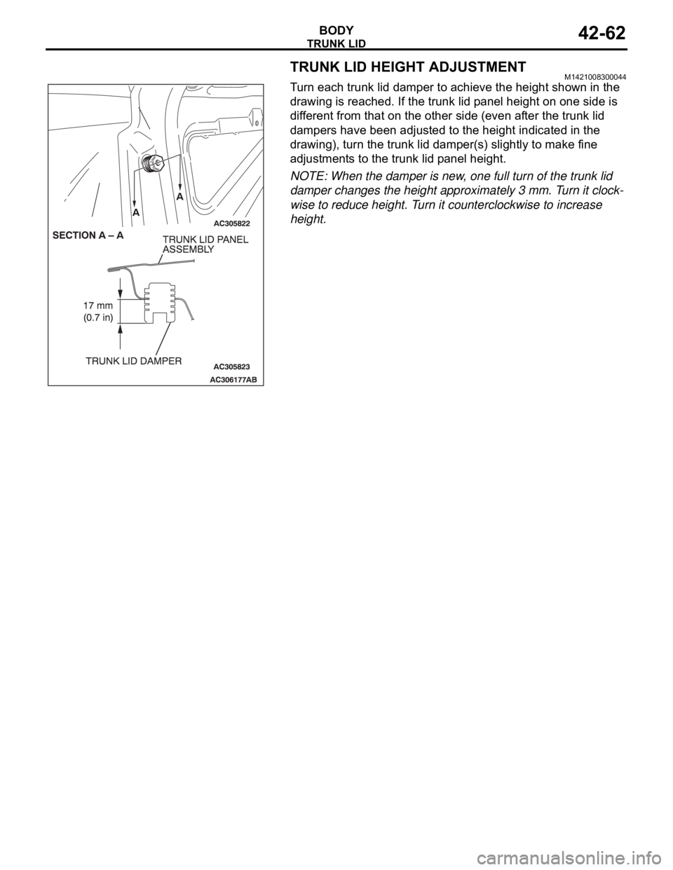
Turn each trunk lid damper to achieve the height shown in the
drawing is reached. If the trunk lid panel height on one side is
different from that on the other side (even after the trunk lid
dampers have been adjusted to the height indicated in the
drawing), turn the trunk lid damper(s) slightly to make fine
adjustments to the trunk lid panel height.
NOTE: When the damper is new, one full turn of the trunk lid
damper changes the height approximately 3 mm. Turn it clock-
wise to reduce height. Turn it counterclockwise to increase
height.
Page 1178 of 1500
ON-VEHICLE SERVICE
BASIC BRAKE SYSTEM35A-13
ON-VEHICLE SERVICE
BRAKE PEDAL CHECK AND ADJUSTMENTM1351000900446
BRAKE PEDAL HEIGHT
1. Turn up the carpet, etc. under the brake pedal.
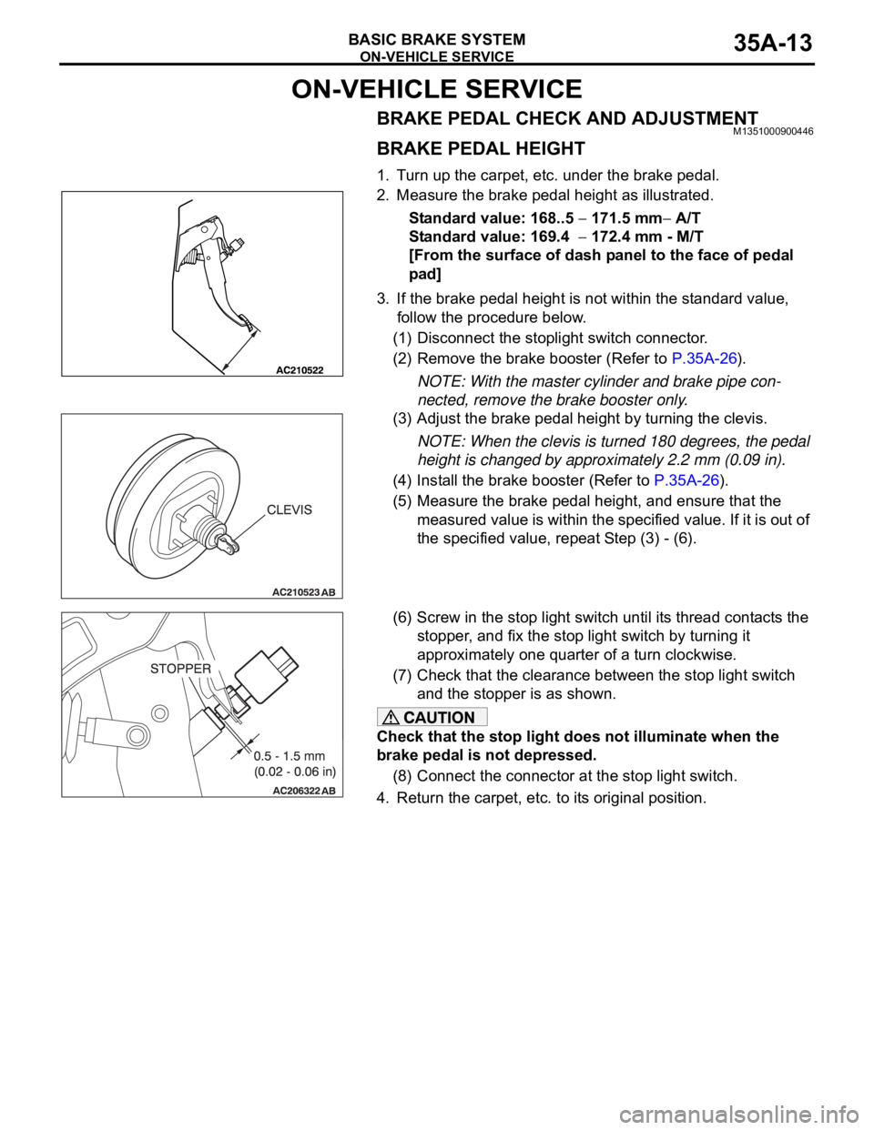
2. Measure the brake pedal height as illustrated.
Standard value: 168..5
171.5 mm A/T
Standard value: 169.4
172.4 mm - M/T
[From the surface of dash panel to the face of pedal
pad]
3. If the brake pedal height is not within the standard value,
follow the procedure below.
(1) Disconnect the stoplight switch connector.
(2) Remove the brake booster (Refer to P.35A-26).
NOTE: With the master cylinder and brake pipe con-
nected, remove the brake booster only.
(3) Adjust the brake pedal height by turning the clevis.
NOTE: When the clevis is turned 180 degrees, the pedal
height is changed by approximately 2.2 mm (0.09 in).
(4) Install the brake booster (Refer to P.35A-26).
(5) Measure the brake pedal height, and ensure that the
measured value is within the specified value. If it is out of
the specified value, repeat Step (3) - (6).
(6) Screw in the stop light switch until its thread contacts the
stopper, and fix the stop light switch by turning it
approximately one quarter of a turn clockwise.
(7) Check that the clearance between the stop light switch
and the stopper is as shown.
Check that the stop light does not illuminate when the
brake pedal is not depressed.
(8) Connect the connector at the stop light switch.
4. Return the carpet, etc. to its original position.
Page 1243 of 1500
PRECAUTIONS BEFORE SERVICE
GENERAL00-22
ENGINE MODEL STAMPING
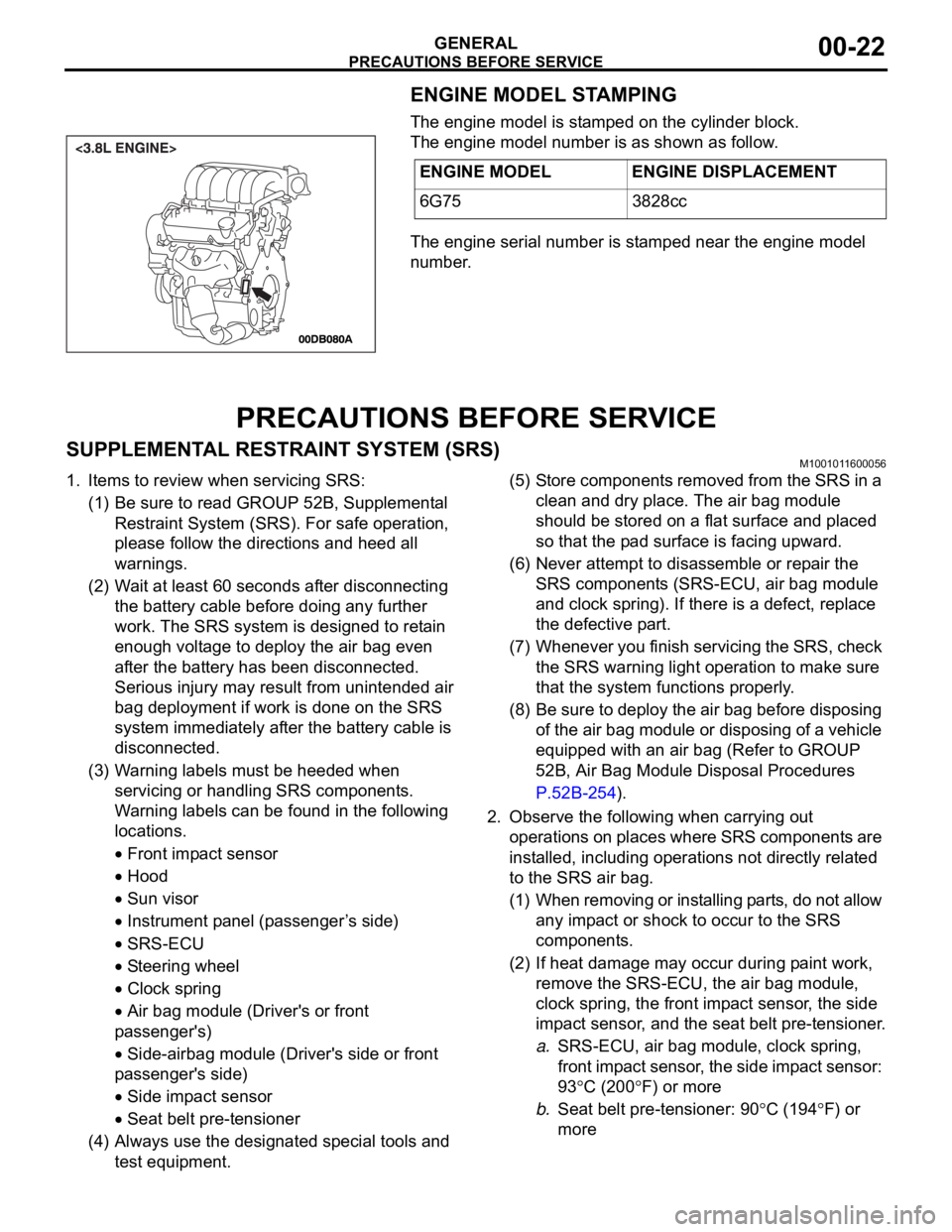
The engine model is stamped on the cylinder block.
The engine model number is as shown as follow.
The engine serial number is stamped near the engine model
number.
PRECAUTIONS BEFORE SERVICE
SUPPLEMENTAL RESTRAINT SYSTEM (SRS)M1001011600056
1. Items to review when servicing SRS:
(1) Be sure to read GROUP 52B, Supplemental
Restraint System (SRS). For safe operation,
please follow the directions and heed all
warnings.
(2) Wait at least 60 seconds after disconnecting
the battery cable before doing any further
work. The SRS system is designed to retain
enough voltage to deploy the air bag even
after the battery has been disconnected.
Serious injury may result from unintended air
bag deployment if work is done on the SRS
system immediately after the battery cable is
disconnected.
(3) Warning labels must be heeded when
servicing or handling SRS components.
Warning labels can be found in the following
locations.
Front impact sensor
Hood
Sun visor
Instrument panel (passenger ’s side)
SRS-ECU
Steering wheel
Clock spring
Air bag module (Driver's or front
passenger's)
Side-airbag module (Driver's side or front
passenger's side)
Side impact sensor
Seat belt pre-tensioner
(4) Always use the designated special tools and
test equipment.(5) Store components removed from the SRS in a
clean and dry place. The air bag module
should be stored on a flat surface and placed
so that the pad surface is facing upward.
(6) Never attempt to disassemble or repair the
SRS components (SRS-ECU, air bag module
and clock spring). If there is a defect, replace
the defective part.
(7) Whenever you finish servicing the SRS, check
the SRS warning light operation to make sure
that the system functions properly.
(8) Be sure to deploy the air bag before disposing
of the air bag module or disposing of a vehicle
equipped with an air bag (Refer to GROUP
52B, Air Bag Module Disposal Procedures
P.52B-254).
2. Observe the following when carrying out
operations on places where SRS components are
installed, including operations not directly related
to the SRS air bag.
(1) When removing or installing parts, do not allow
any impact or shock to occur to the SRS
components.
(2) If heat damage may occur during paint work,
remove the SRS-ECU, the air bag module,
clock spring, the front impact sensor, the side
impact sensor, and the seat belt pre-tensioner.
a.SRS-ECU, air bag module, clock spring,
front impact sensor, the side impact sensor:
93
C (200F) or more
b.Seat belt pre-tensioner: 90
C (194F) or
more ENGINE MODEL ENGINE DISPLACEMENT
6G75 3828cc
Page 1264 of 1500

MAINTENANCE SERVICE
GENERAL00-43
WHEN USING A TENSION GAUGE
Use a belt tension gauge to check that the belt tension is within
the standard value.
Standard value:
.
BELT DEFLECTION CHECK
Apply approximately 98 N (22 lb) of force to the middle of the
drive belt between the pulleys (at the place indicated by the
arrow) and check that the amount of deflection is within the
standard value.
Standard value:
.if the tension or deflection is outside the standard value, adjust
by the following procedure.
1. Loosen the tensioner pulley lock nut.
2. Adjust the belt tension to the standard value by turning the
adjusting bolt. The tension will increase when turning the
adjusting bolt clockwise, and decrease when turning
counterclockwise.
3. Tighten the lock nut to the specified torque.
Tightening torque: 49
9 Nm (36 7 ft-lb)
4. Tighten the adjusting bolt.
Tightening torque: 5.0
1.0 Nm (44 9 in-lb)
Check after turning the crankshaft one or more rotations
clockwise.
5. Check the belt deflection amount and tension, and readjust
if necessary.
ITEM WHEN
CHECKEDDURING
ADJUSTMENTDURING
REPLACEMENT
Te n s i o n N
(lb)294 490
(66
110)343
441
(77
99)490
686
(110
154)
ITEM WHEN
CHECKEDDURING
ADJUSTMENTDURING
REPLACEMENT
Deflection
(Reference
value) mm
(in)12.3 16.2
(0.48
0.64)13.2
15.1
(0.52
0.59)9.6
12.3
(0.38
0.48)
Page 1268 of 1500
MAINTENANCE SERVICE
GENERAL00-47
6. Securely insert the dipstick.
NOTE: The transmission fluid should always be replaced
under the following conditions:
.
When troubleshooting the transaxle.
When overhauling the transaxle.
When the transmission fluid is noticeably dirty or burnt
(driving under severe conditions).
TRANSMISSION FLUID CHANGE
Refer to GROUP 23A, Automatic Transmission - On-vehicle
Service P.23A-296.
12. ENGINE COOLANT (CHANGE)M1001003100357
Check the cooling system parts such as the radiator, heater
and oil cooler hoses, thermostat and their connections for leak-
age and damage.
.
CHANGING COOLANT
1. Set the temperature control knob to the "HOT" position.
2. Run the engine until the engine coolant warms, and then
stop the engine.
When removing the radiator cap, use care to avoid
contact with hot coolant or steam. Place a shop towel
over the cap and turn the cap counterclockwise a lit-
tle to let the pressure escape through the vinyl tube.
After relieving the steam pressure, remove the cap by
slowly turning it counterclockwise.
3. Drain the water from the radiator, heater core and engine
after unplugging the radiator drain plug and removing the
radiator cap.
Page 1274 of 1500
MAINTENANCE SERVICE
GENERAL00-53
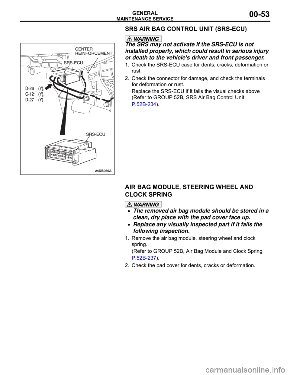
SRS AIR BAG CONTROL UNIT (SRS-ECU)
The SRS may not activate if the SRS-ECU is not
installed properly, which could result in serious injury
or death to the vehicle's driver and front passenger.
1. Check the SRS-ECU case for dents, cracks, deformation or
rust.
2. Check the connector for damage, and check the terminals
for deformation or rust.
Replace the SRS-ECU if it fails the visual checks above
(Refer to GROUP 52B, SRS Air Bag Control Unit
P.52B-234).
AIR BAG MODULE, STEERING WHEEL AND
CLOCK SPRING
The removed air bag module should be stored in a
clean, dry place with the pad cover face up.
Replace any visually inspected part if it fails the
following inspection.
1. Remove the air bag module, steering wheel and clock
spring.
(Refer to GROUP 52B, Air Bag Module and Clock Spring
P.52B-237).
2. Check the pad cover for dents, cracks or deformation.
Page 1275 of 1500
MAINTENANCE SERVICE
GENERAL00-54
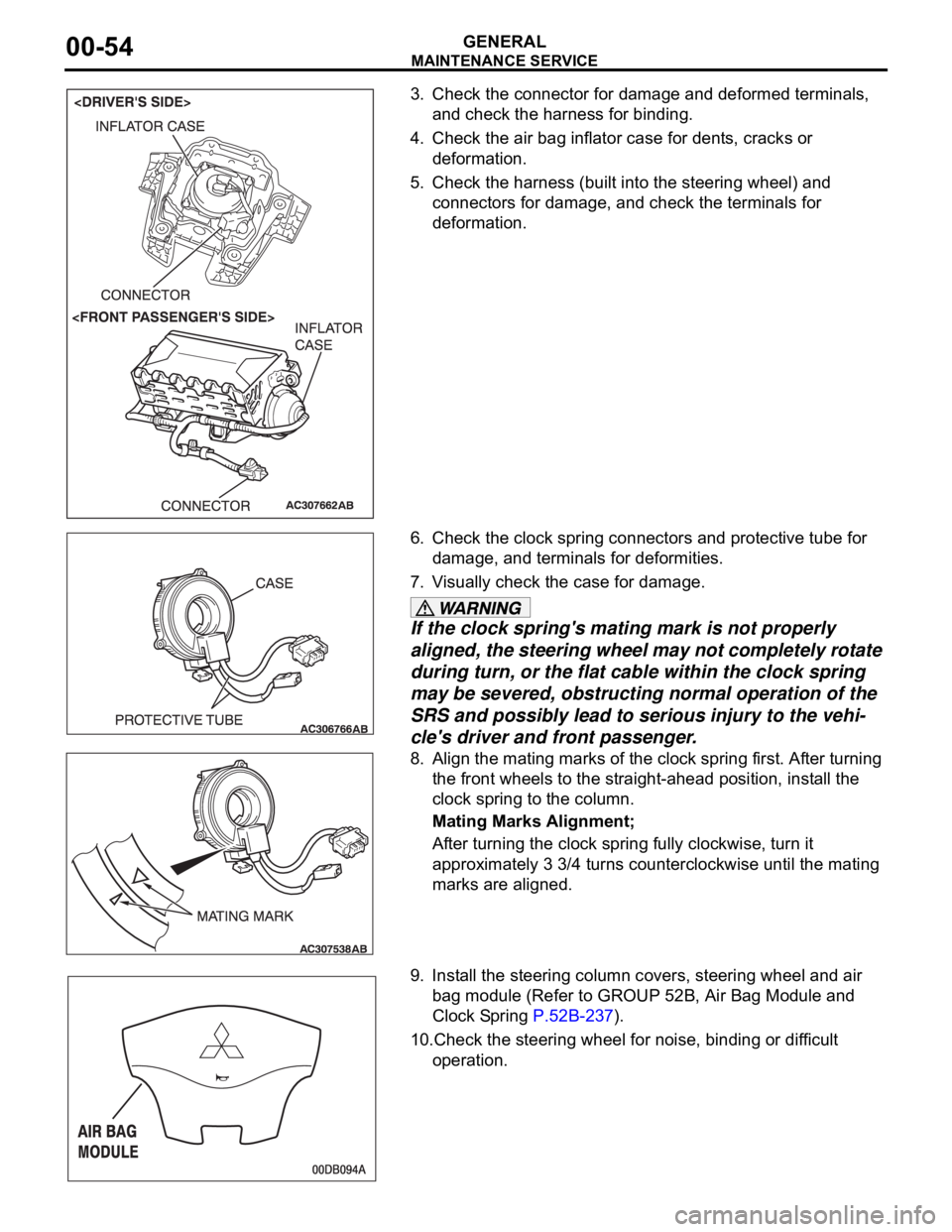
3. Check the connector for damage and deformed terminals,
and check the harness for binding.
4. Check the air bag inflator case for dents, cracks or
deformation.
5. Check the harness (built into the steering wheel) and
connectors for damage, and check the terminals for
deformation.
6. Check the clock spring connectors and protective tube for
damage, and terminals for deformities.
7. Visually check the case for damage.
If the clock spring's mating mark is not properly
aligned, the steering wheel may not completely rotate
during turn, or the flat cable within the clock spring
may be severed, obstructing normal operation of the
SRS and possibly lead to serious injury to the vehi-
cle's driver and front passenger.
8. Align the mating marks of the clock spring first. After turning
the front wheels to the straight-ahead position, install the
clock spring to the column.
Mating Marks Alignment;
After turning the clock spring fully clockwise, turn it
approximately 3 3/4 turns counterclockwise until the mating
marks are aligned.
9. Install the steering column covers, steering wheel and air
bag module (Refer to GROUP 52B, Air Bag Module and
Clock Spring P.52B-237).
10.Check the steering wheel for noise, binding or difficult
operation.
Page 1276 of 1500

MAINTENANCE SERVICE
GENERAL00-55
The SRS may not activate if any of the above compo-
nents are not installed properly, which could result in
serious injury or death to the vehicle's driver and
front passenger.
11.Check the steering wheel for excessive free play.
Replace any part if it fails visual inspection (Refer to
GROUP 52B, Air Bag Module and Clock Spring P.52B-237).
FRONT SEATBACK ASSEMBLY WITH
SIDE-AIRBAG MODULE
If any improper part is found during the following
inspection, replace the front seatback assembly
with a new one.
Dispose of the old one according to the specified
procedure (Refer to GROUP 52B, Air Bag Module
Disposal Procedures P.52B-254).
Never attempt to measure the circuit resistance of
the air bag module (squib) even if you are using
the specified tester. If the circuit resistance is mea-
sured with a tester, accidental air bag deployment
will result in serious personal injury.
1. Check the air bag module deployment section for dents or
deformation.
2. Check the connector for damage; Check the terminals for
deformation; and check the harness for binding.
Replace the front seat if it fails the visual checks above
(Refer to GROUP 52A, Front Seat P.52A-33).
SEAT BELT WITH PRE-TENSIONER
If the seat belt pre-tensioner is not installed
securely and correctly, the seat belt pre-tensioner
may not operate normally.
If a dent, crack, deformation or rust is detected,
replace with a new seat belt pre-tensioner.
1. Check the seat belt pre-tensioner for dents or deformation.
2. Check that the seat belt pre-tensioner is installed correctly to
the vehicle body.
Replace the seat belt pre-tensioner if it fails the visual
checks above (Refer to GROUP 52B, Seat Belt
Pre-tensioner P.52B-250).