Page 1129 of 1500
TRUNK LID
BODY42-62
TRUNK LID HEIGHT ADJUSTMENTM1421008300044
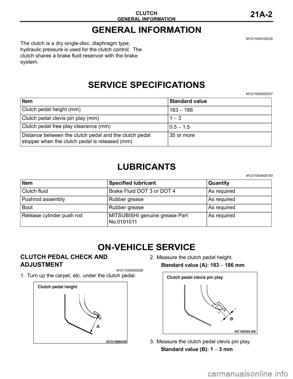
Turn each trunk lid damper to achieve the height shown in the
drawing is reached. If the trunk lid panel height on one side is
different from that on the other side (even after the trunk lid
dampers have been adjusted to the height indicated in the
drawing), turn the trunk lid damper(s) slightly to make fine
adjustments to the trunk lid panel height.
NOTE: When the damper is new, one full turn of the trunk lid
damper changes the height approximately 3 mm. Turn it clock-
wise to reduce height. Turn it counterclockwise to increase
height.
Page 1130 of 1500
TRUNK LID
BODY42-63
TRUNK LID
REMOVAL AND INSTALLATIONM1421002200191
Do not disassemble or throw the trunk lid gas spring into fire.
Punch a hole in the trunk lid gas spring before disposal to release the gas inside.
Ensure the trunk lid gas spring piston rod does not come into contact with foreign material.
Post-installation Operation
Adjustment of Clearance Around Trunk Lid (Refer to
P.42-61).
Trunk Lid Latch Adjustment (Refer to P.42-61).
Trunk Lid Height Adjustment (Refer to P.42-62).
Page 1157 of 1500

GENERAL INFORMATION
CLUTCH21A-2
GENERAL INFORMATION
M1211000100234
The clutch is a dry single-disc, diaphragm type;
hydraulic pressure is used for the clutch control. The
clutch shares a brake fluid reservoir with the brake
system.
SERVICE SPECIFICATIONS
M1211000300227
LUBRICANTS
M1211000400183
ON-VEHICLE SERVICE
CLUTCH PEDAL CHECK AND
ADJUSTMENT
M1211000900285
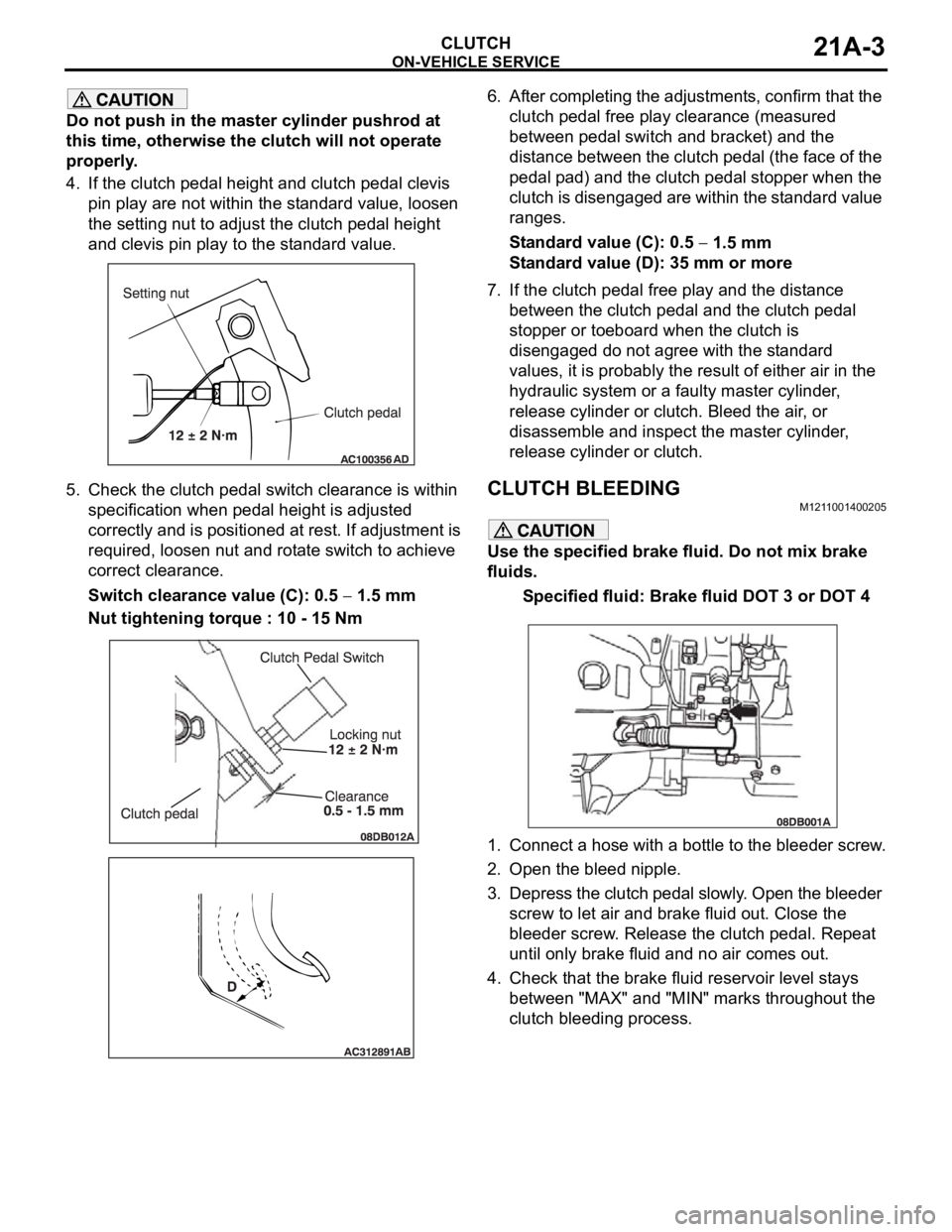
1. Turn up the carpet, etc. under the clutch pedal.2. Measure the clutch pedal height.
Standard value (A): 183
186 mm
3. Measure the clutch pedal clevis pin play.
Standard value (B): 1
3 mm Item Standard value
Clutch pedal height (mm)
183
186
Clutch pedal clevis pin play (mm) 1
3
Clutch pedal free play clearance (mm)
0.5
1.5
Distance between the clutch pedal and the clutch pedal
stopper when the clutch pedal is released (mm)35 or more
Item Specified lubricant Quantity
Clutch fluid Brake Fluid DOT 3 or DOT 4 As required
Pushrod assembly Rubber grease As required
Boot Rubber grease As required
Release cylinder push rod MITSUBISHI genuine grease Part
No.0101011As required
Page 1158 of 1500

ON-VEHICLE SERVICE
CLUTCH21A-3
Do not push in the master cylinder pushrod at
this time, otherwise the clutch will not operate
properly.
4. If the clutch pedal height and clutch pedal clevis
pin play are not within the standard value, loosen
the setting nut to adjust the clutch pedal height
and clevis pin play to the standard value.
5. Check the clutch pedal switch clearance is within
specification when pedal height is adjusted
correctly and is positioned at rest. If adjustment is
required, loosen nut and rotate switch to achieve
correct clearance.
Switch clearance value (C): 0.5
1.5 mm
Nut tightening torque : 10 - 15 Nm6. After completing the adjustments, confirm that the
clutch pedal free play clearance (measured
between pedal switch and bracket) and the
distance between the clutch pedal (the face of the
pedal pad) and the clutch pedal stopper when the
clutch is disengaged are within the standard value
ranges.
Standard value (C): 0.5
1.5 mm
Standard value (D): 35 mm or more
7. If the clutch pedal free play and the distance
between the clutch pedal and the clutch pedal
stopper or toeboard when the clutch is
disengaged do not agree with the standard
values, it is probably the result of either air in the
hydraulic system or a faulty master cylinder,
release cylinder or clutch. Bleed the air, or
disassemble and inspect the master cylinder,
release cylinder or clutch.
CLUTCH BLEEDINGM1211001400205
Use the specified brake fluid. Do not mix brake
fluids.
Specified fluid: Brake fluid DOT 3 or DOT 4
1. Connect a hose with a bottle to the bleeder screw.
2. Open the bleed nipple.
3. Depress the clutch pedal slowly. Open the bleeder
screw to let air and brake fluid out. Close the
bleeder screw. Release the clutch pedal. Repeat
until only brake fluid and no air comes out.
4. Check that the brake fluid reservoir level stays
between "MAX" and "MIN" marks throughout the
clutch bleeding process.
Page 1178 of 1500

ON-VEHICLE SERVICE
BASIC BRAKE SYSTEM35A-13
ON-VEHICLE SERVICE
BRAKE PEDAL CHECK AND ADJUSTMENTM1351000900446
BRAKE PEDAL HEIGHT
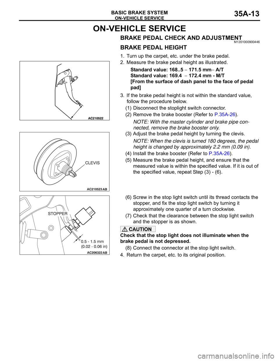
1. Turn up the carpet, etc. under the brake pedal.
2. Measure the brake pedal height as illustrated.
Standard value: 168..5
171.5 mm A/T
Standard value: 169.4
172.4 mm - M/T
[From the surface of dash panel to the face of pedal
pad]
3. If the brake pedal height is not within the standard value,
follow the procedure below.
(1) Disconnect the stoplight switch connector.
(2) Remove the brake booster (Refer to P.35A-26).
NOTE: With the master cylinder and brake pipe con-
nected, remove the brake booster only.
(3) Adjust the brake pedal height by turning the clevis.
NOTE: When the clevis is turned 180 degrees, the pedal
height is changed by approximately 2.2 mm (0.09 in).
(4) Install the brake booster (Refer to P.35A-26).
(5) Measure the brake pedal height, and ensure that the
measured value is within the specified value. If it is out of
the specified value, repeat Step (3) - (6).
(6) Screw in the stop light switch until its thread contacts the
stopper, and fix the stop light switch by turning it
approximately one quarter of a turn clockwise.
(7) Check that the clearance between the stop light switch
and the stopper is as shown.
Check that the stop light does not illuminate when the
brake pedal is not depressed.
(8) Connect the connector at the stop light switch.
4. Return the carpet, etc. to its original position.
Page 1206 of 1500
SPECIFICATIONS
BASIC BRAKE SYSTEM35A-41
SERVICE SPECIFICATIONSM1351000300477
LUBRICANTSM1351000400429
Rear brakes Type Floating caliper, Aluminium housing, 1 piston, ventilated disc
Disc effective dia
thickness
mm 303 18
Wheel cylinder I.D. mm 40.5
Pad thickness mm 10.0
Clearance adjustment Automatic ITEM SPECIFICATION
ITEM STANDARD VALUE LIMIT
Brake pedal height mm A/T 168.5
171.5
M/T 169.4 172.4
Brake pedal free play mm 3
8
Brake pedal to floor board clearance mm 110 or more
Disc brake pad thickness mm 10.0 Minimum 2.0
Disc brake disc thickness
mm Front 28.0 Minimum 26.4
Rear 18.0 Minimum 16.4
Disc brake disc run-out
mm Front
0.1
Rear
0.04
Disc brake drag force N Front 64 or less
Rear 54 or less
Hub end play mm 0.05
Brake booster push rod protruding length mm.
[When applying negative pressure of 66.7 kPa to the
brake booster]5.0
0.1
ITEM SPECIFIED LUBRICANT
Brake fluid DOT3 or DOT4
Piston boot, piston seal Repair kit grease
Front brake pin, rear brake pin (guide pin)