2005 MITSUBISHI 380 check engine light
[x] Cancel search: check engine lightPage 1179 of 1500
ON-VEHICLE SERVICE
BASIC BRAKE SYSTEM35A-14
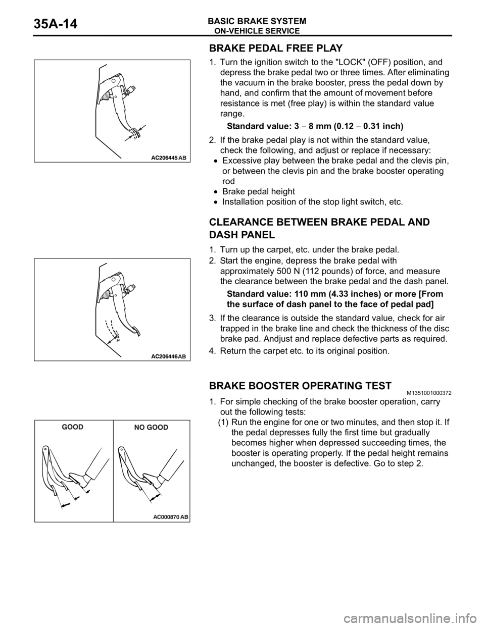
BRAKE PEDAL FREE PLAY
1. Turn the ignition switch to the "LOCK" (OFF) position, and
depress the brake pedal two or three times. After eliminating
the vacuum in the brake booster, press the pedal down by
hand, and confirm that the amount of movement before
resistance is met (free play) is within the standard value
range.
Standard value: 3
8 mm (0.12 0.31 inch)
2. If the brake pedal play is not within the standard value,
check the following, and adjust or replace if necessary:
Excessive play between the brake pedal and the clevis pin,
or between the clevis pin and the brake booster operating
rod
Brake pedal height
Installation position of the stop light switch, etc.
CLEARANCE BETWEEN BRAKE PEDAL AND
DASH PANEL
1. Turn up the carpet, etc. under the brake pedal.
2. Start the engine, depress the brake pedal with
approximately 500 N (112 pounds) of force, and measure
the clearance between the brake pedal and the dash panel.
Standard value: 110 mm (4.33 inches) or more [From
the surface of dash panel to the face of pedal pad]
3. If the clearance is outside the standard value, check for air
trapped in the brake line and check the thickness of the disc
brake pad. Andjust and replace defective parts as required.
4. Return the carpet etc. to its original position.
BRAKE BOOSTER OPERATING TESTM1351001000372
1. For simple checking of the brake booster operation, carry
out the following tests:
(1) Run the engine for one or two minutes, and then stop it. If
the pedal depresses fully the first time but gradually
becomes higher when depressed succeeding times, the
booster is operating properly. If the pedal height remains
unchanged, the booster is defective. Go to step 2.
Page 1180 of 1500
ON-VEHICLE SERVICE
BASIC BRAKE SYSTEM35A-15
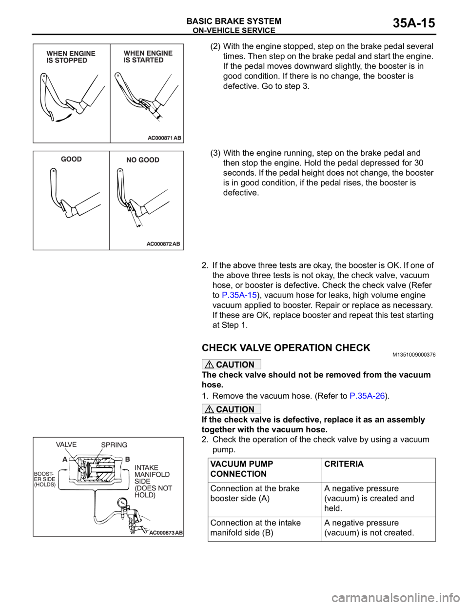
(2) With the engine stopped, step on the brake pedal several
times. Then step on the brake pedal and start the engine.
If the pedal moves downward slightly, the booster is in
good condition. If there is no change, the booster is
defective. Go to step 3.
(3) With the engine running, step on the brake pedal and
then stop the engine. Hold the pedal depressed for 30
seconds. If the pedal height does not change, the booster
is in good condition, if the pedal rises, the booster is
defective.
2. If the above three tests are okay, the booster is OK. If one of
the above three tests is not okay, the check valve, vacuum
hose, or booster is defective. Check the check valve (Refer
to P.35A-15), vacuum hose for leaks, high volume engine
vacuum applied to booster. Repair or replace as necessary.
If these are OK, replace booster and repeat this test starting
at Step 1.
CHECK VALVE OPERATION CHECKM1351009000376
The check valve should not be removed from the vacuum
hose.
1. Remove the vacuum hose. (Refer to P.35A-26).
If the check valve is defective, replace it as an assembly
together with the vacuum hose.
2. Check the operation of the check valve by using a vacuum
pump.
VACUUM PUMP
CONNECTIONCRITERIA
Connection at the brake
booster side (A)A negative pressure
(vacuum) is created and
held.
Connection at the intake
manifold side (B)A negative pressure
(vacuum) is not created.
Page 1243 of 1500
PRECAUTIONS BEFORE SERVICE
GENERAL00-22
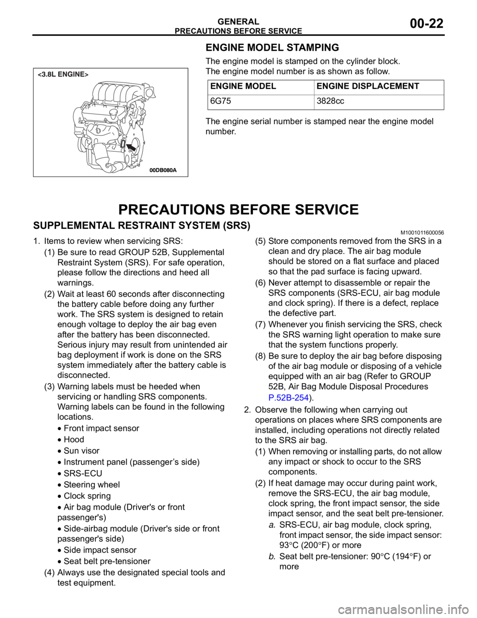
ENGINE MODEL STAMPING
The engine model is stamped on the cylinder block.
The engine model number is as shown as follow.
The engine serial number is stamped near the engine model
number.
PRECAUTIONS BEFORE SERVICE
SUPPLEMENTAL RESTRAINT SYSTEM (SRS)M1001011600056
1. Items to review when servicing SRS:
(1) Be sure to read GROUP 52B, Supplemental
Restraint System (SRS). For safe operation,
please follow the directions and heed all
warnings.
(2) Wait at least 60 seconds after disconnecting
the battery cable before doing any further
work. The SRS system is designed to retain
enough voltage to deploy the air bag even
after the battery has been disconnected.
Serious injury may result from unintended air
bag deployment if work is done on the SRS
system immediately after the battery cable is
disconnected.
(3) Warning labels must be heeded when
servicing or handling SRS components.
Warning labels can be found in the following
locations.
Front impact sensor
Hood
Sun visor
Instrument panel (passenger ’s side)
SRS-ECU
Steering wheel
Clock spring
Air bag module (Driver's or front
passenger's)
Side-airbag module (Driver's side or front
passenger's side)
Side impact sensor
Seat belt pre-tensioner
(4) Always use the designated special tools and
test equipment.(5) Store components removed from the SRS in a
clean and dry place. The air bag module
should be stored on a flat surface and placed
so that the pad surface is facing upward.
(6) Never attempt to disassemble or repair the
SRS components (SRS-ECU, air bag module
and clock spring). If there is a defect, replace
the defective part.
(7) Whenever you finish servicing the SRS, check
the SRS warning light operation to make sure
that the system functions properly.
(8) Be sure to deploy the air bag before disposing
of the air bag module or disposing of a vehicle
equipped with an air bag (Refer to GROUP
52B, Air Bag Module Disposal Procedures
P.52B-254).
2. Observe the following when carrying out
operations on places where SRS components are
installed, including operations not directly related
to the SRS air bag.
(1) When removing or installing parts, do not allow
any impact or shock to occur to the SRS
components.
(2) If heat damage may occur during paint work,
remove the SRS-ECU, the air bag module,
clock spring, the front impact sensor, the side
impact sensor, and the seat belt pre-tensioner.
a.SRS-ECU, air bag module, clock spring,
front impact sensor, the side impact sensor:
93
C (200F) or more
b.Seat belt pre-tensioner: 90
C (194F) or
more ENGINE MODEL ENGINE DISPLACEMENT
6G75 3828cc
Page 1245 of 1500
PRECAUTIONS BEFORE SERVICE
GENERAL00-24
SERVICING ELECTRICAL SYSTEMM1001011900057
Battery posts, terminals and related accessories con-
tain lead and lead compounds. WASH HANDS AFTER
HANDLING.
1. Note the following before proceeding with working on the
electrical system.
Never perform unauthorized modifications to any electrical
device or wiring. Such modifications might lead to a vehicle
malfunction, over-capacity or short-circuit that could result in
a fire in the vehicle.
Before connecting or disconnecting the negative bat-
tery cable, be sure to turn the ignition switch to the
"LOCK" (OFF) position and turn off the lights (If this is
not done, there is the possibility of semiconductor
parts being damaged).
After completion of the work (and the negative battery
terminals is connected), warm up the engine and allow
it to idle for approximately 10 minutes under the condi-
tions described below in order to stabilize engine con-
trol conditions, and then check to be sure that the idle
is satisfactory.
Engine coolant temperature: 85 to 95C (185 to
203
F)
Lights and all accessories: OFF
Transaxle: "N" or "P" position
Steering wheel: straight-forward position
2. When servicing the electrical system, disconnect the
negative cable terminal from the battery.
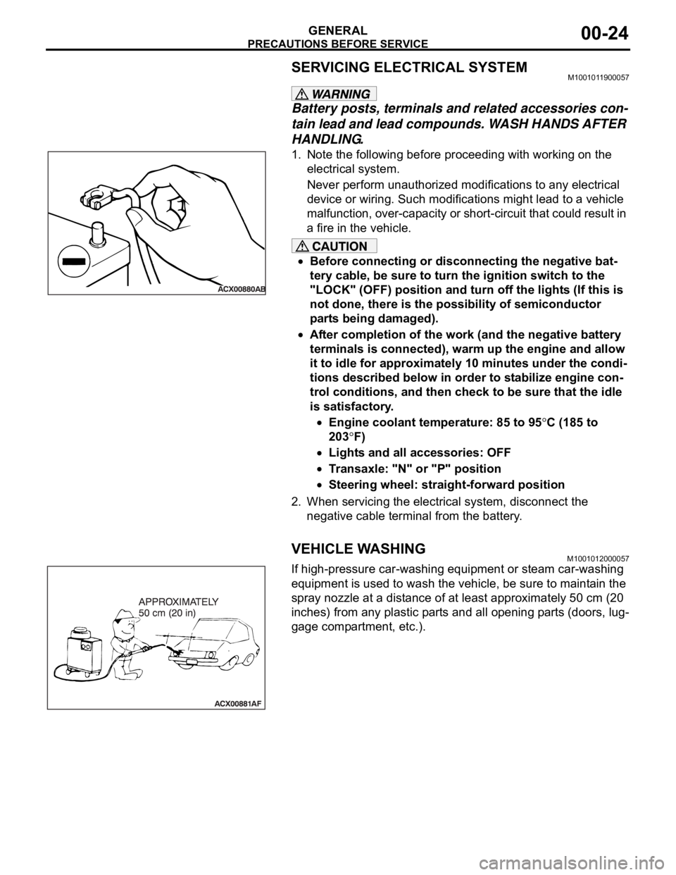
VEHICLE WASHINGM1001012000057
If high-pressure car-washing equipment or steam car-washing
equipment is used to wash the vehicle, be sure to maintain the
spray nozzle at a distance of at least approximately 50 cm (20
inches) from any plastic parts and all opening parts (doors, lug-
gage compartment, etc.).
Page 1326 of 1500
ON-VEHICLE SERVICE
TRACTION CONTROL SYSTEM (TCL)13C-47
ON-VEHICLE SERVICE
TCL INDICATOR LIGHT CHECKM1136000900058
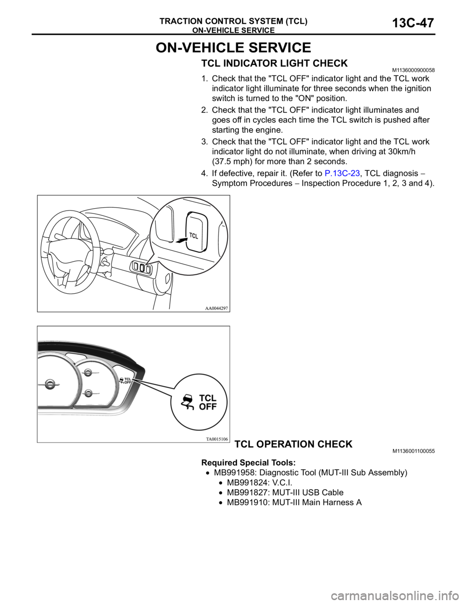
1. Check that the "TCL OFF" indicator light and the TCL work
indicator light illuminate for three seconds when the ignition
switch is turned to the "ON" position.
2. Check that the "TCL OFF" indicator light illuminates and
goes off in cycles each time the TCL switch is pushed after
starting the engine.
3. Check that the "TCL OFF" indicator light and the TCL work
indicator light do not illuminate, when driving at 30km/h
(37.5 mph) for more than 2 seconds.
4. If defective, repair it. (Refer to P.13C-23, TCL diagnosis
Symptom Procedures
Inspection Procedure 1, 2, 3 and 4).
TCL OPERATION CHECKM1136001100055
Required Special Tools:
MB991958: Diagnostic Tool (MUT-III Sub Assembly)
MB991824: V.C.I.
MB991827: MUT-III USB Cable
MB991910: MUT-III Main Harness A
Page 1399 of 1500

AUTO-CRUISE CONTROL
ENGINE AND EMISSION CONTROL17-68
If the air intake duct is removed from the throttle body take great care to keep fingers away
from the throttle plate. The drive motor has very high torque and is capable of random move-
ment at any time. Do not under any circumstances activate the throttle plate by hand.
When removing the throttle body from the intake manifold disconnect the wiring first. During
replacement connect the wiring last.
Do not activate the throttle body using a DC suppy to test the motor,as permanent damage to
the throttle body will result.
10 (B-20) Throttle position
sensor power supplyIgnition switch: "ON" 4.9 5.1 V
57 (B-20) Throttle position
sensor (sub)(1) Accelerator pedal:
Released
(2) Accelerator pedal:
Depressed(1) Throttle
valve fully
closed1035
1250 mV
(2) Throttle
valve fully open4000 mV or more
42 (B-20) Throttle position
sensor (main)(1) Accelerator pedal:
Released
(2) Accelerator pedal:
Depressed(1) Throttle
valve fully
closed1035
1250 mV
(2) Throttle
valve fully open4000 mV or more
49 (B-20) Throttle actuator
control motor (
)
Ignition switch: "ON"
Accelerator pedal: fully closed to fully
openedDecreases slightly
(approx. 2 V) from
battery voltage.
50 (B-20) Throttle actuator
control motor (+)
Ignition switch: "ON"
Accelerator pedal: fully opened to fully
closedDecreases slightly
(approx. 2 V) from
battery voltage. TERMINAL
NO.CHECK ITEM CHECK CONDITION NORMAL
CONDITION
Page 1404 of 1500
AUTO-CRUISE CONTROL
ENGINE AND EMISSION CONTROL17-73
AUTO-CRUISE CONTROL SYSTEM COMPONENT
CHECK
M1172001700316
AUTO-CRUISE CONTROL SWITCH CHECK
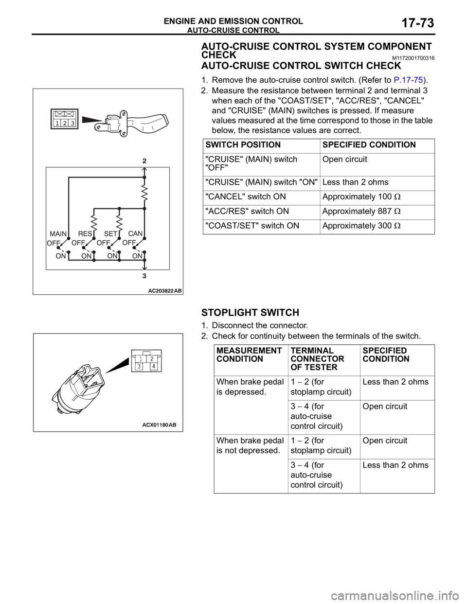
1. Remove the auto-cruise control switch. (Refer to P.17-75).
2. Measure the resistance between terminal 2 and terminal 3
when each of the "COAST/SET", "ACC/RES", "CANCEL"
and "CRUISE" (MAIN) switches is pressed. If measure
values measured at the time correspond to those in the table
below, the resistance values are correct.
STOPLIGHT SWITCH
1. Disconnect the connector.
2. Check for continuity between the terminals of the switch.SWITCH POSITION SPECIFIED CONDITION
"CRUISE" (MAIN) switch
"OFF"Open circuit
"CRUISE" (MAIN) switch "ON" Less than 2 ohms
"CANCEL" switch ON Approximately 100
"ACC/RES" switch ON Approximately 887
"COAST/SET" switch ON Approximately 300
MEASUREMENT
CONDITIONTERMINAL
CONNECTOR
OF TESTERSPECIFIED
CONDITION
When brake pedal
is depressed.1
2 (for
stoplamp circuit)Less than 2 ohms
3
4 (for
auto-cruise
control circuit)Open circuit
When brake pedal
is not depressed.1
2 (for
stoplamp circuit)Open circuit
3
4 (for
auto-cruise
control circuit)Less than 2 ohms
Page 1414 of 1500
EMISSION CONTROL
ENGINE AND EMISSION CONTROL17-83
Required Special Tool:
MB995061: Purge Flow Indicator
1. Disconnect the purge hose from the evaporative emission
(EVAP) purge solenoid, and connect special tool MB995061
between the EVAP purge solenoid and the purge hose.
2. Before inspection, set the vehicle in the following conditions:
Engine coolant temperature: 80 95C (176 203F)
Lights, electric cooling fan and accessories: OFF
Transaxle: P range
3. Run the engine at idle for more than four minutes.
4. Check the purge flow volume when engine is revved
suddenly several times.
Standard value: Momentarily 20 cm
3/s (2.5 SCFH) or
more.
5. If the purge flow volume is less than the standard value,
check it again with the vacuum hose disconnected from the
EVAP canister. If the purge flow volume is less than the
standard value, check the vacuum port and the vacuum
hose for clogging. Also check the EVAP purge solenoid. If
the purge flow volume is at the standard value, replace the
EVAP canister.
EVAPORATIVE EMISSION PURGE SOLENOID
CHECK
M1173001700289
1. Disconnect the vacuum hose (black, black with red paint
mark) from the evaporative emission (EVAP) purge
solenoid.
NOTE: When disconnecting the vacuum hose, always place
an identification mark so that it can be reconnected at its
original position.
2. Disconnect the harness connector.
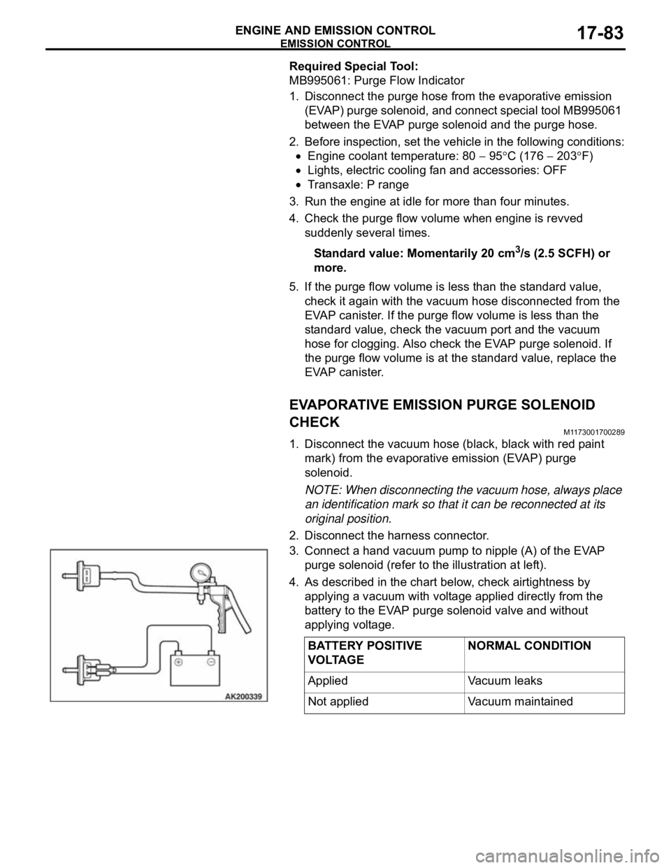
3. Connect a hand vacuum pump to nipple (A) of the EVAP
purge solenoid (refer to the illustration at left).
4. As described in the chart below, check airtightness by
applying a vacuum with voltage applied directly from the
battery to the EVAP purge solenoid valve and without
applying voltage.
BATTERY POSITIVE
VOLTAGENORMAL CONDITION
Applied Vacuum leaks
Not applied Vacuum maintained