Page 1323 of 1500
TRACTION CONTROL SYSTEM (TCL) DIAGNOSIS
TRACTION CONTROL SYSTEM (TCL)13C-44
Connect oscilloscope to FL sensor signal terminal (5) at
ABS-ECU (A-02)
Connect oscilloscope to FR sensor signal terminal (10)
at ABS-ECU (A-02)
Connect oscilloscope to RL sensor signal terminal (17)
at ABS-ECU (A-02)
Connect oscilloscope to RR sensor signal terminal (19)
at ABS-ECU (A-02)
(7) Recommended Oscilloscope setting:
Y-axis: 2Volts
X-axis: 100ms
(8) Turn the ignition switch to the "ON" position.
(9) Turn wheel by hand at approximately 1 revolution per
second (r/sec) or drive on brake dynamometer at 5km/h.
The measurement reading of the active wheel speed sen-
sors on the oscilloscope should correspond to figure 3
below.
NOTE: If the oscilloscope signal shape is correct and wheel
sensor air gap is within specification, but the voltage values are
either higher or lower as shown in the table below, the wheel
speed sensor must be changed.
Page 1345 of 1500

AUTO-CRUISE CONTROL
ENGINE AND EMISSION CONTROL17-14
To prevent damage to Diagnostic Tool MB991958, always
turn the ignition switch to the "LOCK" (OFF) position
before connecting or disconnecting Diagnostic Tool
MB991958.
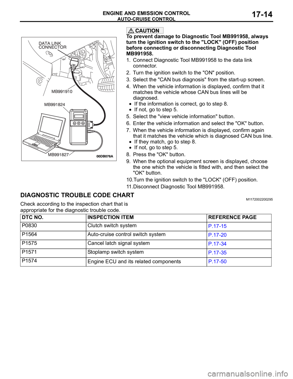
1. Connect Diagnostic Tool MB991958 to the data link
connector.
2. Turn the ignition switch to the "ON" position.
3. Select the "CAN bus diagnosis" from the start-up screen.
4. When the vehicle information is displayed, confirm that it
matches the vehicle whose CAN bus lines will be
diagnosed.
If the information is correct, go to step 8.
If not, go to step 5.
5. Select the "view vehicle information" button.
6. Enter the vehicle information and select the "OK" button.
7. When the vehicle information is displayed, confirm again
that it matches the vehicle which is diagnosed CAN bus line.
If they match, go to step 8.
If not, go to step 5.
8. Press the "OK" button.
9. When the optional equipment screen is displayed, choose
the one which the vehicle is fitted with, and then select the
"OK" button.
10.Turn the ignition switch to the "LOCK" (OFF) position.
11.Disconnect Diagnostic Tool MB991958.
DIAGNOSTIC TROUBLE CODE CHARTM1172002200295
Check according to the inspection chart that is
appropriate for the diagnostic trouble code.
DTC NO. INSPECTION ITEM REFERENCE PAGE
P0830 Clutch switch system
P.17-15
P1564 Auto-cruise control switch system
P.17-20
P1575 Cancel latch signal system
P.17-34
P1571 Stoplamp switch system
P.17-35
P1574
Engine ECU and its related componentsP.17-50
Page 1391 of 1500

AUTO-CRUISE CONTROL
ENGINE AND EMISSION CONTROL17-60
INSPECTION PROCEDURE 6: Hunting (Repeated Acceleration and Deceleration) Occurs at the Set
Vehicle Speed.
.
COMMENT
The output shaft speed sensor signal or the throttle
body is suspected.
.
TROUBLESHOOTING HINTS (THE MOST
LIKELY CAUSES FOR THIS CASE:)
Malfunction of the output shaft speed sensor.
Malfunction of the throttle body.
Malfunction of the Engine ECU.
Malfunction of the A/T ECU.
Circuit drawings
Refer to circuit diagrams GROUP-90
Refer to configuration diagrams GROUP-80
Refer to component locations GROUP-70
DIAGNOSIS
Required Special Tools:
MB991958: Diagnostic Tool (MUT-III Sub Assembly)
MB991824: V.C.I.
MB991827: MUT-III USB Cable
MB991910: MUT-III Main Harness A
STEP 1. Using Diagnostic Tool MB991958, read the
diagnostic trouble code.
To prevent damage to Diagnostic Tool MB991958, always
turn the ignition switch to the "LOCK" (OFF) position
before connecting or disconnecting Diagnostic Tool
MB991958.
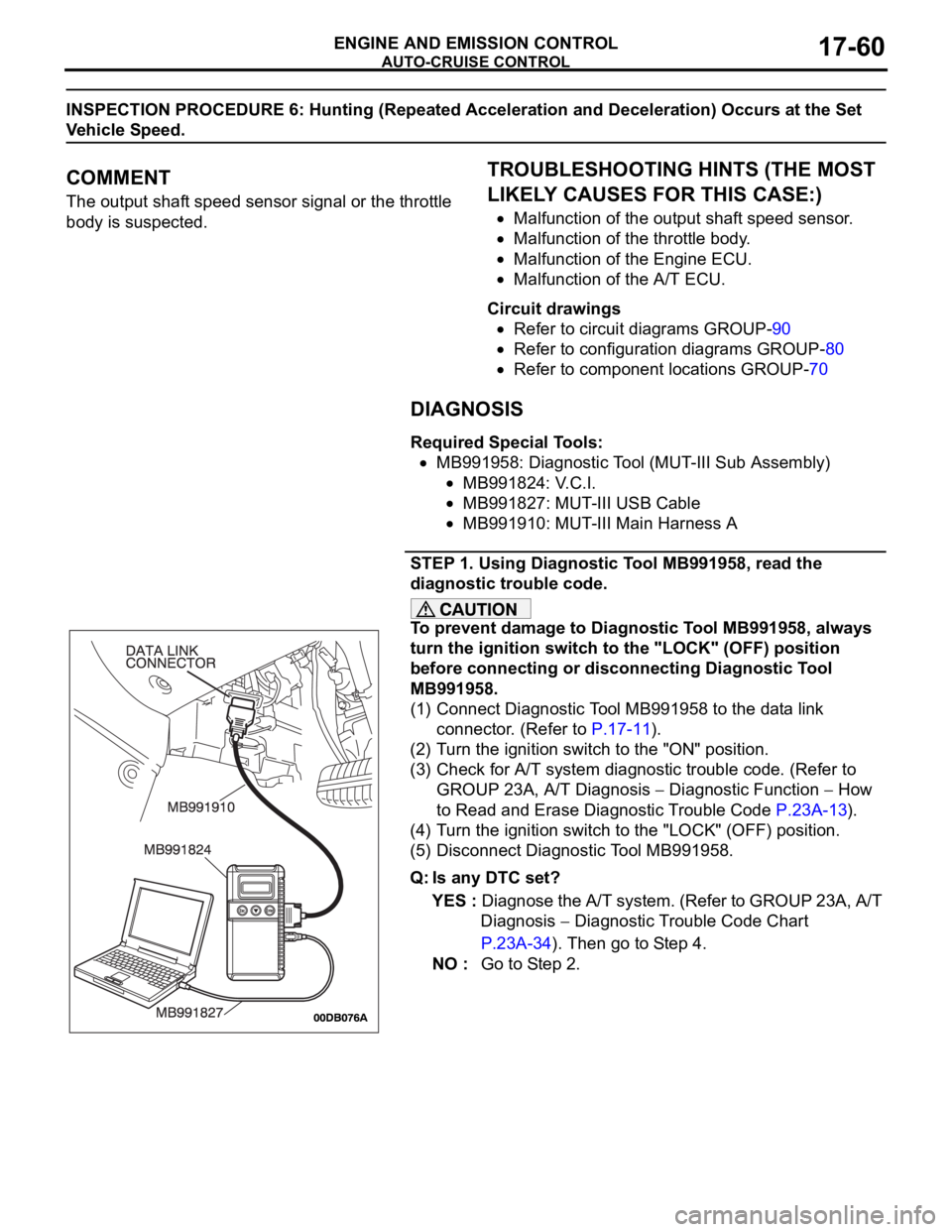
(1) Connect Diagnostic Tool MB991958 to the data link
connector. (Refer to P.17-11).
(2) Turn the ignition switch to the "ON" position.
(3) Check for A/T system diagnostic trouble code. (Refer to
GROUP 23A, A/T Diagnosis
Diagnostic Function How
to Read and Erase Diagnostic Trouble Code P.23A-13).
(4) Turn the ignition switch to the "LOCK" (OFF) position.
(5) Disconnect Diagnostic Tool MB991958.
Q: Is any DTC set?
YES : Diagnose the A/T system. (Refer to GROUP 23A, A/T
Diagnosis
Diagnostic Trouble Code Chart
P.23A-34). Then go to Step 4.
NO : Go to Step 2.
Page 1394 of 1500

AUTO-CRUISE CONTROL
ENGINE AND EMISSION CONTROL17-63
CIRCUIT OPERATION
The Engine ECU detects "CRUISE" (MAIN) switch
"ON" signal to illuminate the "CRUISE" indicator
lamp on the combination meter.
.
COMMENT
Connector(s), wiring harness in the CAN bus line
between the Engine ECU and the combination
meter, power supply to the Engine ECU, the combi-
nation meter, the Engine ECU may be defective.
.
TROUBLESHOOTING HINTS
Malfunction of the combination meter.
Damaged harness or connector.
Malfunction of the Engine ECU.
Circuit drawings
Refer to circuit diagrams GROUP-90
Refer to configuration diagrams GROUP-80
Refer to component locations GROUP-70
DIAGNOSIS
Required Special Tools:
MB991958: Diagnostic Tool (MUT-III Sub Assembly)
MB991824: V.C.I.
MB991827: MUT-III USB Cable
MB991910: MUT-III Main Harness A
STEP 1. Using Diagnostic Tool MB991958, diagnose the
CAN bus line.
To prevent damage to Diagnostic Tool MB991958, always
turn the ignition switch to the "LOCK" (OFF) position
before connecting or disconnecting Diagnostic Tool
MB991958.
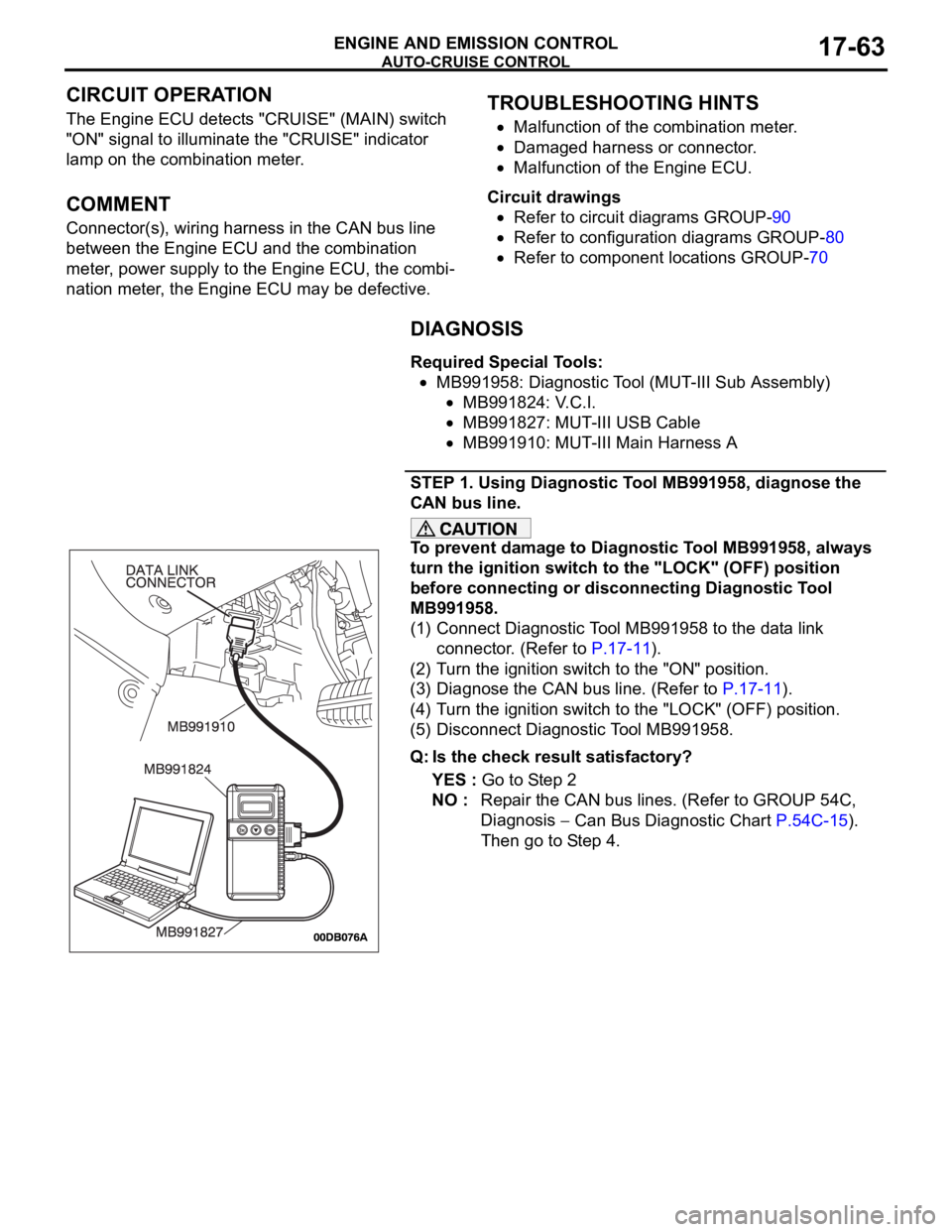
(1) Connect Diagnostic Tool MB991958 to the data link
connector. (Refer to P.17-11).
(2) Turn the ignition switch to the "ON" position.
(3) Diagnose the CAN bus line. (Refer to P.17-11).
(4) Turn the ignition switch to the "LOCK" (OFF) position.
(5) Disconnect Diagnostic Tool MB991958.
Q: Is the check result satisfactory?
YES : Go to Step 2
NO : Repair the CAN bus lines. (Refer to GROUP 54C,
Diagnosis
Can Bus Diagnostic Chart P.54C-15).
Then go to Step 4.
Page 1477 of 1500

AUTOMATIC TRANSMISSION DIAGNOSIS
AUTOMATIC TRANSMISSION23A-18
FAIL-SAFE/BACKUP FUNCTIONM1231008300234
When a malfunction of a main sensor or actuator is
detected by the A/T-ECU, the transmission is con-
trolled by pre-set control logic to maintain safe condi-
tions for driving.The following table shows how the fail-safe/backup
function affects vehicle driveability and operation.
MALFUNCTIONING ITEM JUDGEMENT
CONDITIONCONTROL DEFAULT DURING MALFUNCTION
Input shaft speed sensor If no output pulse
from the input shaft
speed sensor is
detected for one
second or more
when the vehicle
speed is 30 km/h (19
mph) or greater.The diagnostic trouble code is recorded when the
malfunction occurs during 4 monitoring periods in
one drive cycle. When the judgment condition is
met, the transmission holds 3rd gear or 2nd gear,
depending on speed, as a fail-safe.
Output shaft speed sensor The output signal
from the output shaft
speed sensor is not
present for one
second or more
while the vehicle is
driven.The diagnostic trouble code is recorded when the
malfunction occurs during 4 monitoring periods in
one drive cycle. When the judgment condition is
met, the transmission holds 3rd gear or 2nd gear,
depending on speed, as a fail-safe.
Low-reverse solenoid valve Solenoid valve
resistance is below
2.7 ohms for 0.32
seconds.The diagnostic trouble code is recorded when the
malfunction occurs during 5 monitoring periods in
one drive cycle. When the judgment condition is
met, the A/T control relay is turned off. The
transmission will only operate in 3rd and reverse
gears until the system is repaired. Underdrive solenoid valve
Second solenoid valve
Overdrive solenoid valve
Reduction (RED) solenoid valve
Damper control clutch (DCC)
solenoid valve
Incomplete shifting 1st The gear ratio value
from the output shaft
speed sensor is not
the same as the
output from the input
shaft speed sensor
for one second after
shifting has been
completed.The diagnostic trouble code is recorded when the
malfunction occurs during 5 monitoring periods in
one drive cycle. When the judgment condition is
met, the A/T control relay is turned off. The
transmission will only operate in 3rd and reverse
gears until the system is repaired. 2nd
3rd
4th
5th
Reverse
A/T control relay A/T control relay
voltage is less than
seven volts for 0.1
second after the
ignition switch is
turned "ON."The A/T control relay is switched off. The
transmission will only operate in 3rd and reverse
gears until the system is repaired.
Malfunction in the A/T-ECU Malfunction has
occurred in the
A/T-ECU.The A/T control relay is switched off. The
transmission will only operate in 3rd and reverse
gears until the system is repaired.