2005 MITSUBISHI 380 brake rotor
[x] Cancel search: brake rotorPage 1166 of 1500
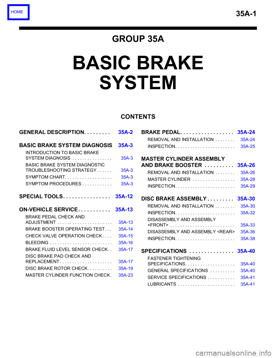
35A-1
GROUP 35A
BASIC BRAKE
SYSTEM
CONTENTS
GENERAL DESCRIPTION. . . . . . . . .35A-2
BASIC BRAKE SYSTEM DIAGNOSIS35A-3
INTRODUCTION TO BASIC BRAKE
SYSTEM DIAGNOSIS . . . . . . . . . . . . . . . . 35A-3
BASIC BRAKE SYSTEM DIAGNOSTIC
TROUBLESHOOTING STRATEGY . . . . . . 35A-3
SYMPTOM CHART. . . . . . . . . . . . . . . . . . . 35A-3
SYMPTOM PROCEDURES . . . . . . . . . . . . 35A-3
SPECIAL TOOLS . . . . . . . . . . . . . . . .35A-12
ON-VEHICLE SERVICE . . . . . . . . . . .35A-13
BRAKE PEDAL CHECK AND
ADJUSTMENT . . . . . . . . . . . . . . . . . . . . . . 35A-13
BRAKE BOOSTER OPERATING TEST . . . 35A-14
CHECK VALVE OPERATION CHECK . . . . 35A-15
BLEEDING . . . . . . . . . . . . . . . . . . . . . . . . . 35A-16
BRAKE FLUID LEVEL SENSOR CHECK. . 35A-17
DISC BRAKE PAD CHECK AND
REPLACEMENT . . . . . . . . . . . . . . . . . . . . . 35A-17
DISC BRAKE ROTOR CHECK . . . . . . . . . . 35A-19
MASTER CYLINDER FUNCTION CHECK . 35A-23
BRAKE PEDAL. . . . . . . . . . . . . . . . . .35A-24
REMOVAL AND INSTALLATION . . . . . . . . 35A-24
INSPECTION. . . . . . . . . . . . . . . . . . . . . . . . 35A-25
MASTER CYLINDER ASSEMBLY
AND BRAKE BOOSTER . . . . . . . . . .35A-26
REMOVAL AND INSTALLATION . . . . . . . . 35A-26
MASTER CYLINDER . . . . . . . . . . . . . . . . . 35A-28
INSPECTION. . . . . . . . . . . . . . . . . . . . . . . . 35A-29
DISC BRAKE ASSEMBLY . . . . . . . . .35A-30
REMOVAL AND INSTALLATION . . . . . . . . 35A-30
INSPECTION. . . . . . . . . . . . . . . . . . . . . . . . 35A-32
DISASSEMBLY AND ASSEMBLY
DISASSEMBLY AND ASSEMBLY
INSPECTION. . . . . . . . . . . . . . . . . . . . . . . . 35A-38
SPECIFICATIONS . . . . . . . . . . . . . . .35A-40
FASTENER TIGHTENING
SPECIFICATIONS. . . . . . . . . . . . . . . . . . . . 35A-40
GENERAL SPECIFICATIONS . . . . . . . . . . 35A-40
SERVICE SPECIFICATIONS . . . . . . . . . . . 35A-41
LUBRICANTS . . . . . . . . . . . . . . . . . . . . . . . 35A-41
Page 1167 of 1500
GENERAL DESCRIPTION
BASIC BRAKE SYSTEM35A-2
GENERAL DESCRIPTIONM1351000100440
The brake system has been designed to give greater
reliability and durability and to provide excellent brak-
ing performance.
FEATURES
.
Improved braking performance
1. An 8+9 inch tandem brake booster provides suffi-
cient braking force in sudden braking range.
2. 296mm front ventilated disc brakes provide sta-
ble braking force and improved braking feel.
3. 303mm rear ventillated disc brakes are used.
.
Improved stability
1. A 4-wheel anti-lock braking system (4ABS) pre-
vents slipping caused by the vehicle wheels lock-
ing up, in order to maintain a stable vehicle
posture and steering performance.
2. An electronic brake-force distribution (EBD)
makes it possible to maintain the maximum
amount of braking force even when the vehicle's
load is unevenly distributed. 3. Front- and rear-wheel X-type brake line layout
are used.
4. Ventilated discs brakes improve anti-fading per-
formance.
.
Improved serviceability
1. A diagnosis function for the ABS system makes
inspection easier.
2. An outer disc separated hub and rotor make
removal and installation easier.
3. The master cylinder reservoir is utilised for both
brake and clutch fluid on manual transmission
vehicles.
4. The master cylinder filter is coloured black for
improved viewing.
5. The ABS-ECU and hydraulic unit are integrated
to make them more compact and light weight.
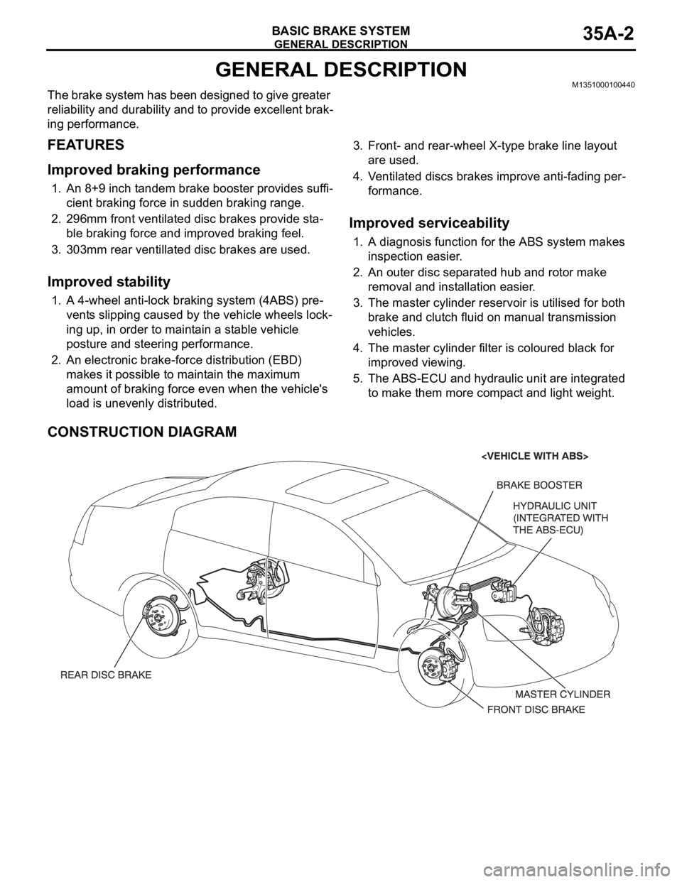
CONSTRUCTION DIAGRAM
Page 1174 of 1500
BASIC BRAKE SYSTEM DIAGNOSIS
BASIC BRAKE SYSTEM35A-9
STEP 3. Adjust the brake pedal or brake booster
pushrod.
Refer to P.35A-13 or P.35A-26.
Q: Are the brake pedal and the brake booster pushrod
adjusted correctly?
YES :
Go to Step 4.
NO : Adjust the brake pedal or the brake booster
pushrod. Then go to Step 4.
STEP 4. Recheck symptom.
Q: Is the symptom eliminated?
YES :
The procedure is complete.
NO : Start over at step 1. If a new symptom
surfaces, refer to the symptom chart.
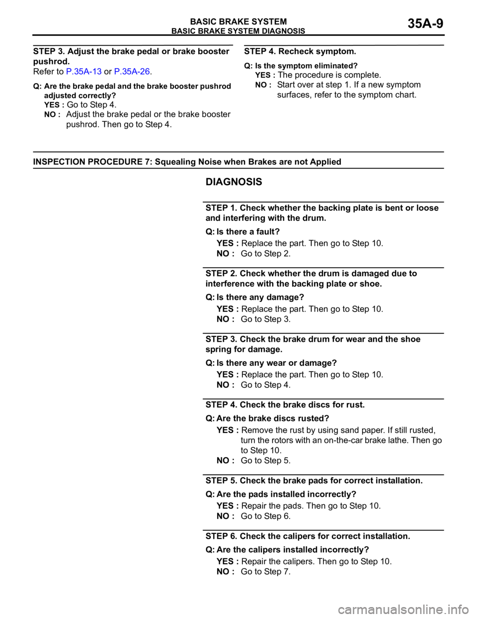
INSPECTION PROCEDURE 7: Squealing Noise when Brakes are not Applied
DIAGNOSIS
.
STEP 1. Check whether the backing plate is bent or loose
and interfering with the drum.
Q: Is there a fault?
YES : Replace the part. Then go to Step 10.
NO : Go to Step 2.
STEP 2. Check whether the drum is damaged due to
interference with the backing plate or shoe.
Q: Is there any damage?
YES : Replace the part. Then go to Step 10.
NO : Go to Step 3.
STEP 3. Check the brake drum for wear and the shoe
spring for damage.
Q: Is there any wear or damage?
YES : Replace the part. Then go to Step 10.
NO : Go to Step 4.
STEP 4. Check the brake discs for rust.
Q: Are the brake discs rusted?
YES : Remove the rust by using sand paper. If still rusted,
turn the rotors with an on-the-car brake lathe. Then go
to Step 10.
NO : Go to Step 5.
STEP 5. Check the brake pads for correct installation.
Q: Are the pads installed incorrectly?
YES : Repair the pads. Then go to Step 10.
NO : Go to Step 6.
STEP 6. Check the calipers for correct installation.
Q: Are the calipers installed incorrectly?
YES : Repair the calipers. Then go to Step 10.
NO : Go to Step 7.
Page 1182 of 1500
ON-VEHICLE SERVICE
BASIC BRAKE SYSTEM35A-17
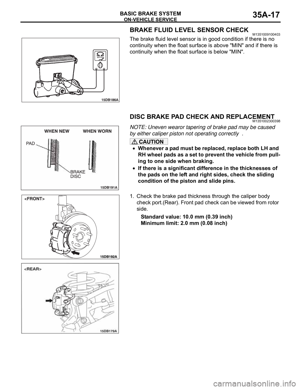
BRAKE FLUID LEVEL SENSOR CHECKM1351009100403
The brake fluid level sensor is in good condition if there is no
continuity when the float surface is above "MIN" and if there is
continuity when the float surface is below "MIN".
DISC BRAKE PAD CHECK AND REPLACEMENTM1351002300398
NOTE: Uneven wearor tapering of brake pad may be caused
by either caliper piston not operating correctly .
Whenever a pad must be replaced, replace both LH and
RH wheel pads as a set to prevent the vehicle from pull-
ing to one side when braking.
If there is a significant difference in the thicknesses of
the pads on the left and right sides, check the sliding
condition of the piston and slide pins.
1. Check the brake pad thickness through the caliper body
check port.(Rear). Front pad check can be viewed from rotor
side.
Standard value: 10.0 mm (0.39 inch)
Minimum limit: 2.0 mm (0.08 inch)
Page 1184 of 1500
ON-VEHICLE SERVICE
BASIC BRAKE SYSTEM35A-19
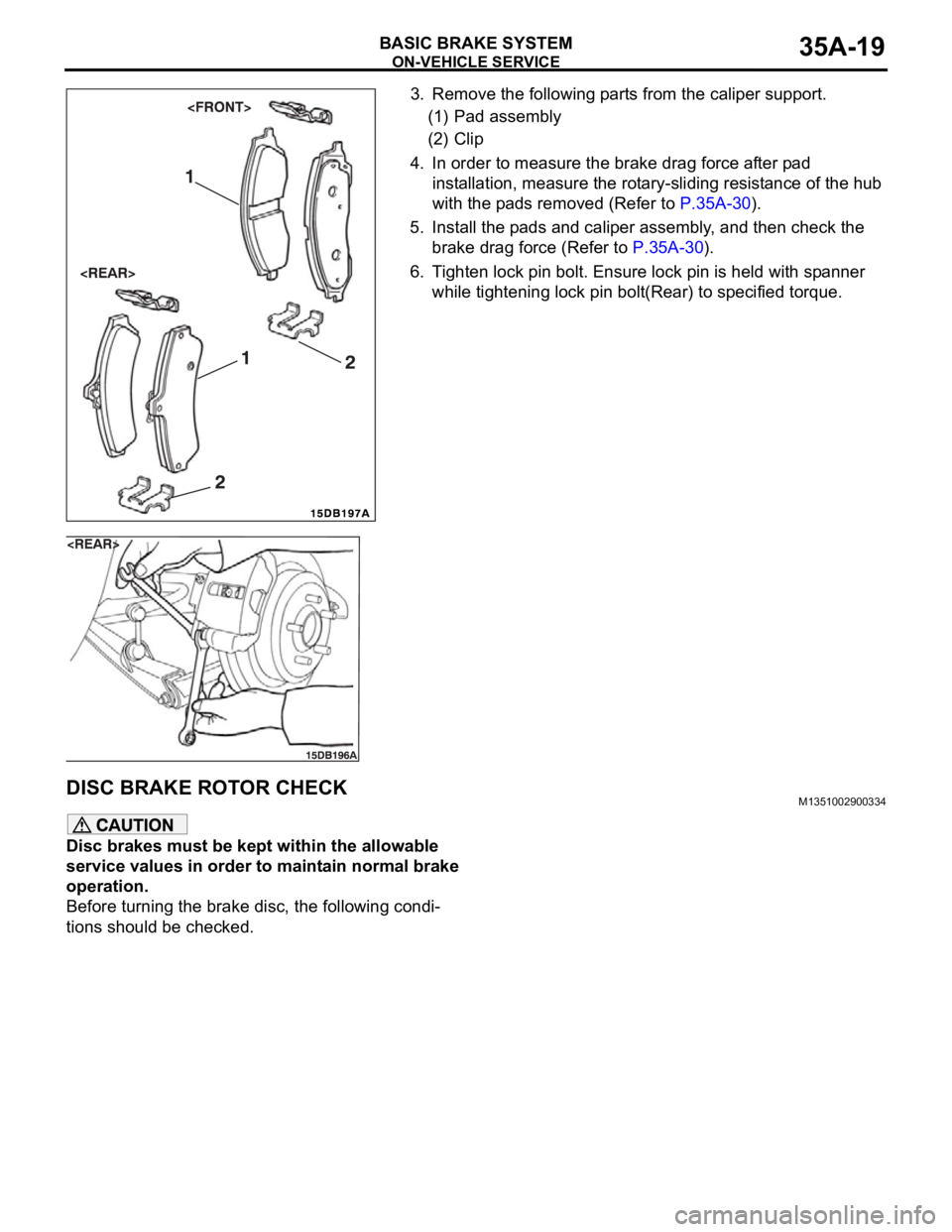
3. Remove the following parts from the caliper support.
(1) Pad assembly
(2) Clip
4. In order to measure the brake drag force after pad
installation, measure the rotary-sliding resistance of the hub
with the pads removed (Refer to P.35A-30).
5. Install the pads and caliper assembly, and then check the
brake drag force (Refer to P.35A-30).
6. Tighten lock pin bolt. Ensure lock pin is held with spanner
while tightening lock pin bolt(Rear) to specified torque.
DISC BRAKE ROTOR CHECKM1351002900334
Disc brakes must be kept within the allowable
service values in order to maintain normal brake
operation.
Before turning the brake disc, the following condi-
tions should be checked.
Page 1186 of 1500
ON-VEHICLE SERVICE
BASIC BRAKE SYSTEM35A-21
After a new brake disc is installed, always grind the
brake disc with an on-the-car type brake lathe. If this
step is not carried out, the brake disc run-out exceeds
the specified value, resulting in judder.
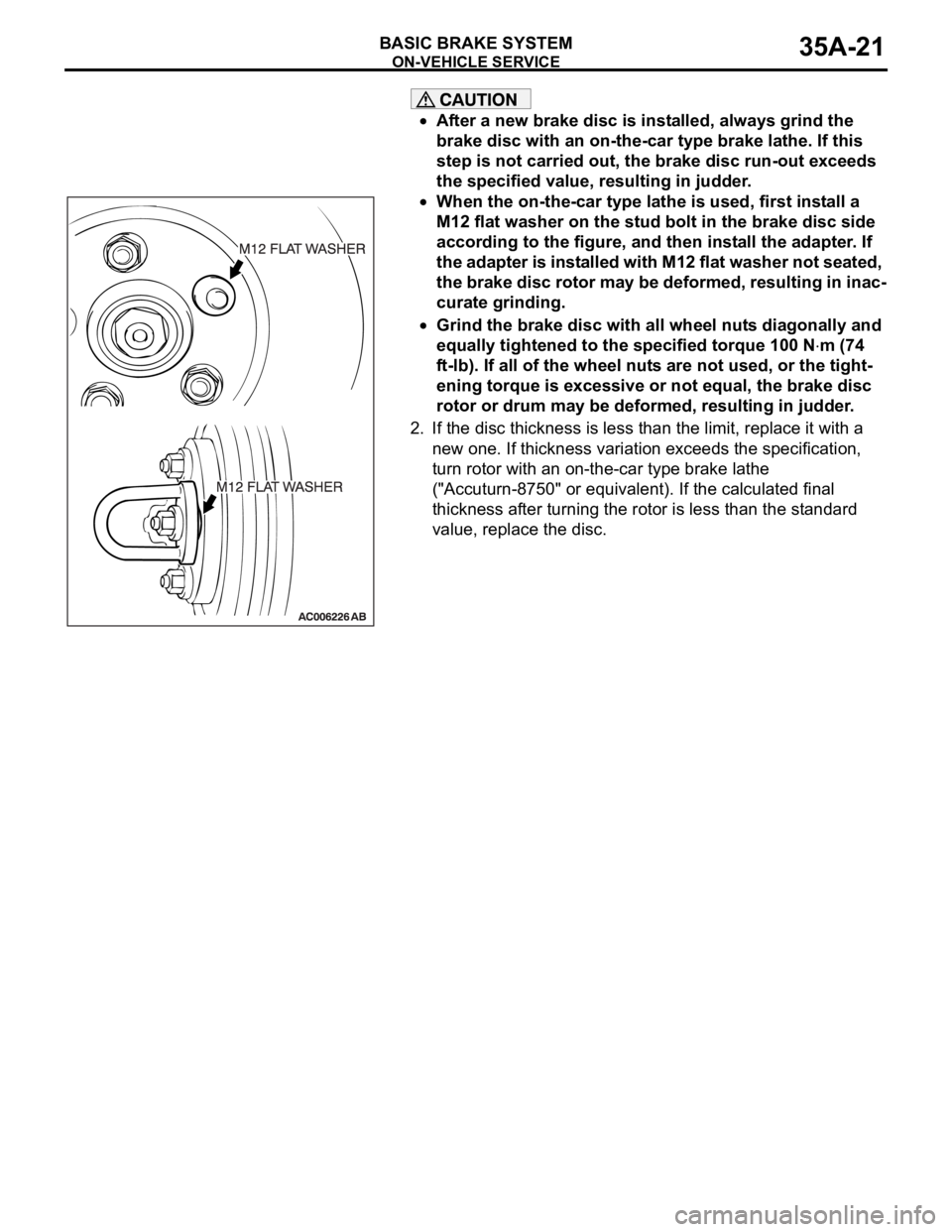
When the on-the-car type lathe is used, first install a
M12 flat washer on the stud bolt in the brake disc side
according to the figure, and then install the adapter. If
the adapter is installed with M12 flat washer not seated,
the brake disc rotor may be deformed, resulting in inac-
curate grinding.
Grind the brake disc with all wheel nuts diagonally and
equally tightened to the specified torque 100 N
m (74
ft-lb). If all of the wheel nuts are not used, or the tight-
ening torque is excessive or not equal, the brake disc
rotor or drum may be deformed, resulting in judder.
2. If the disc thickness is less than the limit, replace it with a
new one. If thickness variation exceeds the specification,
turn rotor with an on-the-car type brake lathe
("Accuturn-8750" or equivalent). If the calculated final
thickness after turning the rotor is less than the standard
value, replace the disc.
.
Page 1188 of 1500
ON-VEHICLE SERVICE
BASIC BRAKE SYSTEM35A-23
After a new brake disc is installed, always grind the
brake disc with an on-the-car type brake lathe. If this
step is not carried out, the brake disc run-out exceeds
the specified value, resulting in judder.
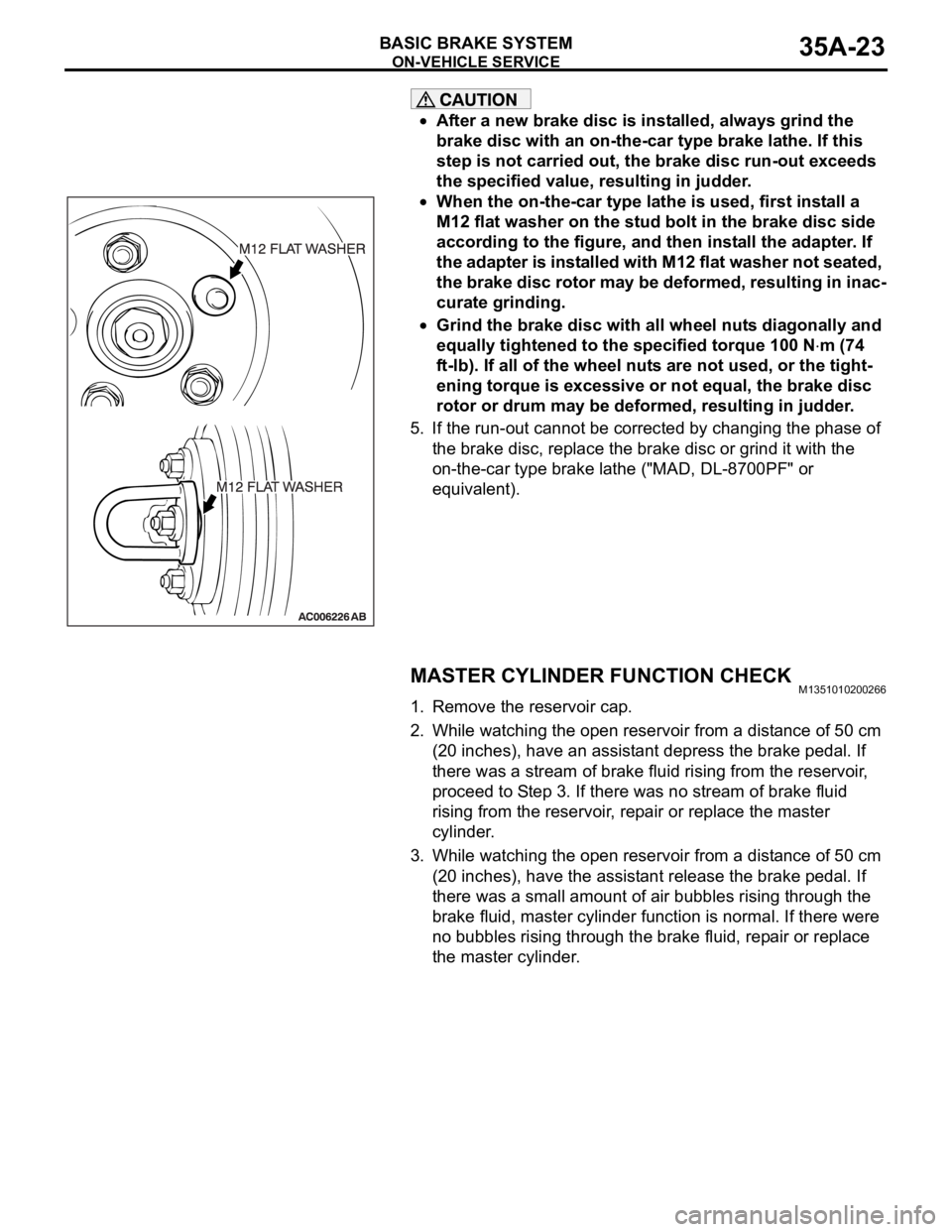
When the on-the-car type lathe is used, first install a
M12 flat washer on the stud bolt in the brake disc side
according to the figure, and then install the adapter. If
the adapter is installed with M12 flat washer not seated,
the brake disc rotor may be deformed, resulting in inac-
curate grinding.
Grind the brake disc with all wheel nuts diagonally and
equally tightened to the specified torque 100 N
m (74
ft-lb). If all of the wheel nuts are not used, or the tight-
ening torque is excessive or not equal, the brake disc
rotor or drum may be deformed, resulting in judder.
5. If the run-out cannot be corrected by changing the phase of
the brake disc, replace the brake disc or grind it with the
on-the-car type brake lathe ("MAD, DL-8700PF" or
equivalent).
MASTER CYLINDER FUNCTION CHECKM1351010200266
1. Remove the reservoir cap.
2. While watching the open reservoir from a distance of 50 cm
(20 inches), have an assistant depress the brake pedal. If
there was a stream of brake fluid rising from the reservoir,
proceed to Step 3. If there was no stream of brake fluid
rising from the reservoir, repair or replace the master
cylinder.
3. While watching the open reservoir from a distance of 50 cm
(20 inches), have the assistant release the brake pedal. If
there was a small amount of air bubbles rising through the
brake fluid, master cylinder function is normal. If there were
no bubbles rising through the brake fluid, repair or replace
the master cylinder.
Page 1223 of 1500
GENERAL00-2
MAINTENANCE SERVICE . . . . . . . .00-37
1. FUEL SYSTEM (TANK, PIPE LINE AND
CONNECTION, AND FUEL TANK FILLER
TUBE CAP) (CHECK FOR LEAKS) . . . . . . 00-37
2. FUEL HOSES (CHECK CONDITION) . . 00-37
3. AIR CLEANER FILTER (REPLACE). . . . 00-37
4. EVAPORATIVE EMISSION SYSTEM
(EXCEPT EVAPORATIVE EMISSION
CANISTER) (CHECK FOR CLOGGING) . . 00-37
5. SPARK PLUGS (REPLACE). . . . . . . . . . 00-38
7. TIMING BELT (REPLACE) . . . . . . . . . . . 00-38
8. DRIVE BELTS (FOR ALTERNATOR, POWER
STEERING PUMP AND AIR CONDITIONING)
(CHECK) . . . . . . . . . . . . . . . . . . . . . . . . . . . 00-39
9. EXHAUST SYSTEM (CONNECTIONS
PORTION OF MUFFLER, MUFFLER PIPES
AND CONVERTER HEAT SHIELDS) (CHECK
AND SERVICE AS REQUIRED) . . . . . . . . . 00-44
10. ENGINE OIL (CHANGE) . . . . . . . . . . . . 00-4411. ENGINE OIL FILTER (REPLACE) . . . . 00-44
12. TRANSMISSION FLUID . . . . . . . . . . . . 00-45
13. ENGINE COOLANT (CHANGE) . . . . . . 00-47
14. COOLANT HOSES (RADIATOR HOSE,
HEATER HOSE) (INSPECT). . . . . . . . . . . . 00-49
15. DISC BRAKE PADS, ROTORS
(INSPECT FOR WEAR) . . . . . . . . . . . . . . . 00-49
16. BRAKE HOSES (CHECK FOR
DETERIORATION OR LEAKS) . . . . . . . . . . 00-49
17. BALL JOINT AND STEERING LINKAGE
SEALS (INSPECT FOR GREASE LEAKS
AND DAMAGE) . . . . . . . . . . . . . . . . . . . . . . 00-50
18. DRIVE SHAFT BOOTS (INSPECT FOR
GREASE LEAKS AND DAMAGE) . . . . . . . . 00-50
19. SUSPENSION SYSTEM (INSPECT FOR
LOOSENESS AND DAMAGE) . . . . . . . . . . 00-51
20. SRS AIR BAG (INSPECT FOR SRS
SYSTEM). . . . . . . . . . . . . . . . . . . . . . . . . . . 00-51
21. TYRES (ROTATE). . . . . . . . . . . . . . . . . 00-58