Page 161 of 304

•All-Wheel driving capability (if applicable)
•Load leveling adjustment (if applicable)
When driving with the dissimilar spare tire/wheel additional caution
should be given to:
•Towing a trailer
•Driving vehicles equipped with a camper body
•Driving vehicles with a load on the cargo rack
Drive cautiously when using a dissimilar spare tire/wheel and seek
service as soon as possible.
Stopping and securing the vehicle
1. If you get a flat tire while driving,
do not apply the brake heavily;
instead, gradually decrease your
speed. Hold the steering wheel
firmly and slowly move to a safe
place on the side of the road.
2. Park on a level surface, activate
the hazard flashers and set the
parking brake.
3. Place gearshift lever in P (Park)
and turn engine OFF.
When one of the rear wheels is off the ground, the transmission
alone will not prevent the vehicle from moving or slipping off the
jack, even if the transmission is in P (Park).
Note:Passengers should not remain
in the vehicle when the vehicle is
being jacked.
4. Block the wheel that is diagonally
opposite of the flat tire using the
wheel chock provided with your
vehicle.
2005 Mountaineer(mnt)
Owners Guide (post-2002-fmt)
USA(fus)
Tires, Wheels and Loading
161
Page 162 of 304
Location of the spare tire and tools
The spare tire and tools for your vehicle are stowed in the following
locations:
Tool Location
Spare tire Under the vehicle, just in front of
the rear bumper. The spare tire
winch drive nut is located at the
rear center of the cargo area
under a lid.
Jack, lug nut wrench, jack handle,
wheel chockBehind the rear seat under the
carpeted floor lid in the cargo
floor. The tools are located in a
bag attached to the jack.
Removing the jack and tools
1. Open liftgate and remove the
carpeted floor lid, then the jack.
2. Turn jack screw eyelet
counterclockwise and remove the
jack from the bracket.
3. Remove the tools from the
provided bag.
2005 Mountaineer(mnt)
Owners Guide (post-2002-fmt)
USA(fus)
Tires, Wheels and Loading
162
Page 163 of 304
Rotate the wrench socket out from
the handle.
Removing the spare tire
Do not use an impact wrench on the winch drive nut. This will
damage the spare tire winch.
1. Open the cover from the carpeting on cargo floor to expose the winch
drive nut.
2. Insert the lug wrench on the
winch drive nut.
The wrench will stop moving and
forward resistance to turning will be
felt when properly engaged.
2005 Mountaineer(mnt)
Owners Guide (post-2002-fmt)
USA(fus)
Tires, Wheels and Loading
163
Page 164 of 304

3. Turn the wrench
counterclockwise until the tire is
lowered to the ground and the cable
has slack. When turning the wrench,
make sure that it does not scuff the
kick plate.
4. Slide the tire rearward, lift one
side and remove the retainer from
the spare tire.
Changing the spare tire
To prevent the vehicle from moving when you change a tire, be
sure the parking brake is set, then block the wheel that is
diagonally opposite (other end of the vehicle) to the tire being
changed.
If the vehicle slips off the jack, you or someone else could be
seriously injured.
Do not attempt to change a tire on the side of the vehicle close
to moving traffic. Pull far enough off the road to avoid the
danger of being hit when operating the jack or changing the wheel.
1. Use the tip of the lug wrench to
remove the beauty cap by twisting
the tip under the cap. The carpeted
floor lid can be used as a kneeling
pad.
2. Loosen each wheel lug nut by half
a turn, but do not remove them
until the wheel is raised off the
ground.
2005 Mountaineer(mnt)
Owners Guide (post-2002-fmt)
USA(fus)
Tires, Wheels and Loading
164
Page 165 of 304
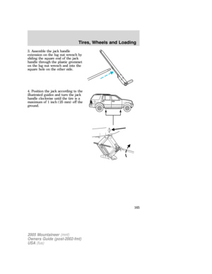
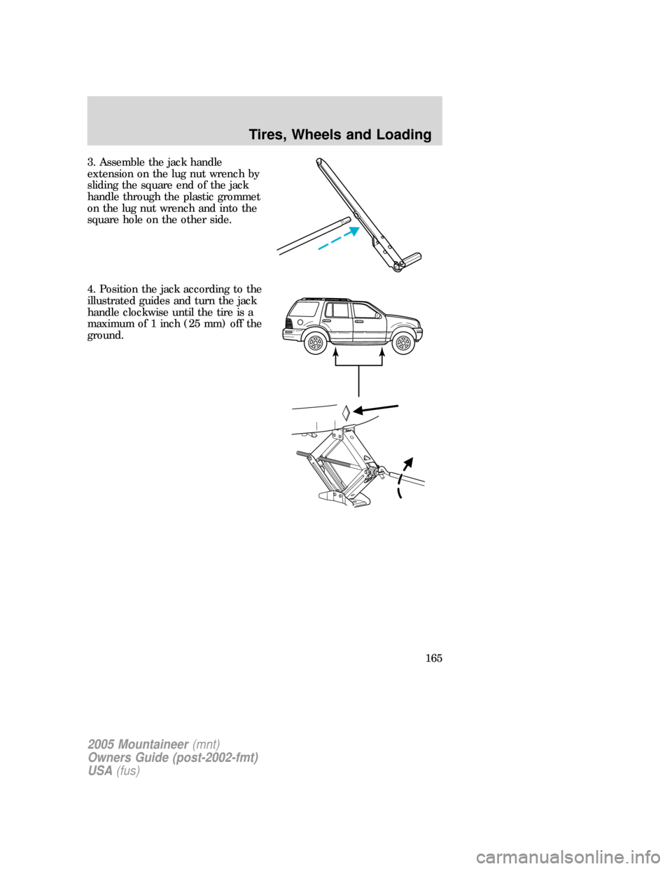
3. Assemble the jack handle
extension on the lug nut wrench by
sliding the square end of the jack
handle through the plastic grommet
on the lug nut wrench and into the
square hole on the other side.
4. Position the jack according to the
illustrated guides and turn the jack
handle clockwise until the tire is a
maximum of 1 inch (25 mm) off the
ground.
2005 Mountaineer(mnt)
Owners Guide (post-2002-fmt)
USA(fus)
Tires, Wheels and Loading
165
Page 166 of 304

To lessen the risk of
personal injury, do not put
any part of your body under the
vehicle while changing a tire. Do
not start the engine when your
vehicle is on the jack. The jack is
only meant for changing the tire.
•Never use the front or rear
differential as a jacking point.
5. Remove the lug nuts with the lug wrench.
6. Replace the flat tire with the spare tire, making sure the valve stem is
facing outward. Reinstall the lug nuts, cone side in, until the wheel is
snug against the hub. Do not fully tighten the lug nuts until the wheel
has been lowered.
7. Lower the wheel by turning the jack handle counterclockwise.
8. Remove the jack and fully tighten
the lug nuts in the order shown.
Refer toWheel lug nut torque
specificationslater in this chapter
for the proper lug nut torque
specification.
Stowing the flat/spare tire
Note:Failure to follow spare tire stowage instructions may result in
failure of cable or loss of spare tire.
1. Lay the tire on the ground with the valve stem facing up, toward the
vehicle.
2. Slide the wheel partially under the vehicle and install the retainer
through the wheel center. Pull on the cable to align the components at
the end of the cable.
1
4 3
2 5
2005 Mountaineer(mnt)
Owners Guide (post-2002-fmt)
USA(fus)
Tires, Wheels and Loading
166
Page 167 of 304

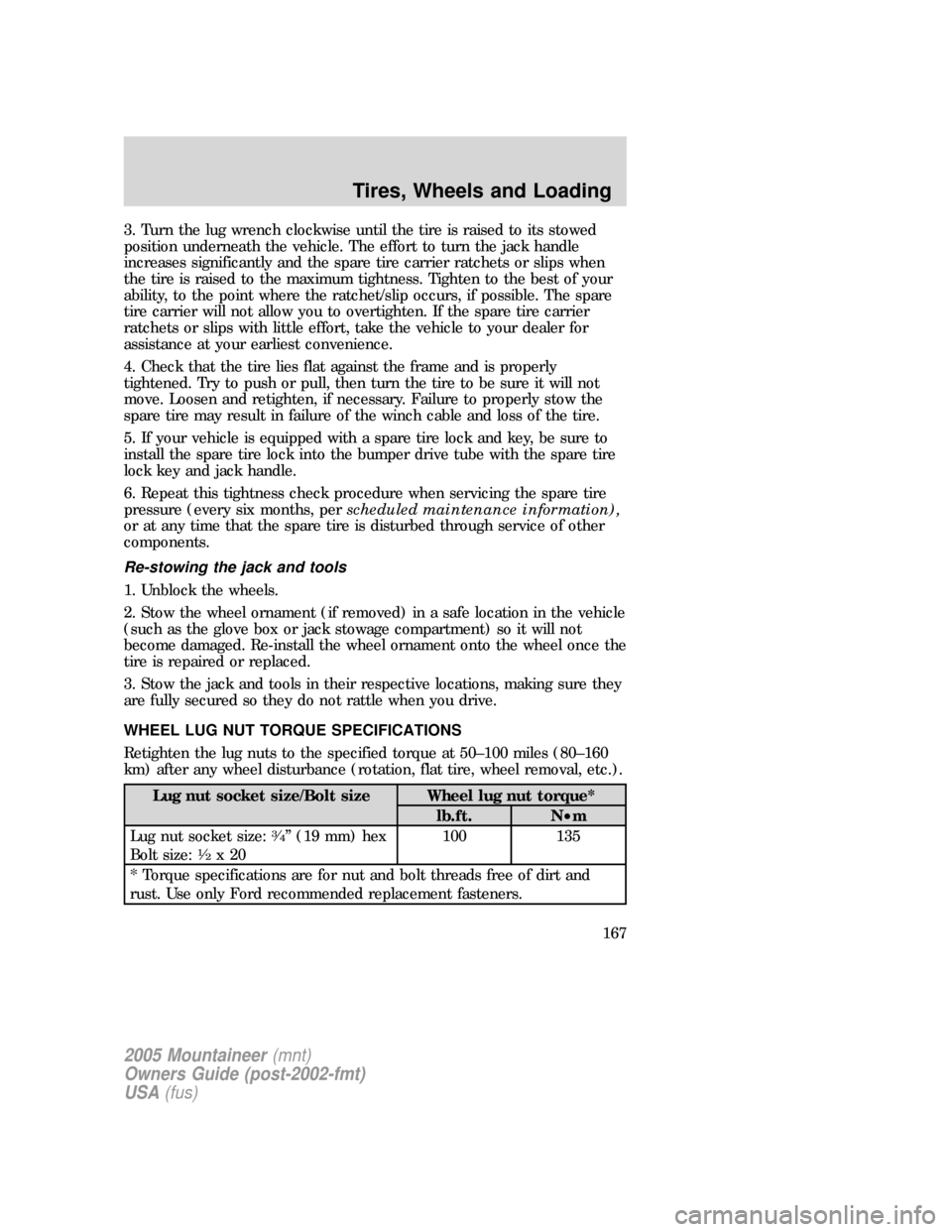
3. Turn the lug wrench clockwise until the tire is raised to its stowed
position underneath the vehicle. The effort to turn the jack handle
increases significantly and the spare tire carrier ratchets or slips when
the tire is raised to the maximum tightness. Tighten to the best of your
ability, to the point where the ratchet/slip occurs, if possible. The spare
tire carrier will not allow you to overtighten. If the spare tire carrier
ratchets or slips with little effort, take the vehicle to your dealer for
assistance at your earliest convenience.
4. Check that the tire lies flat against the frame and is properly
tightened. Try to push or pull, then turn the tire to be sure it will not
move. Loosen and retighten, if necessary. Failure to properly stow the
spare tire may result in failure of the winch cable and loss of the tire.
5. If your vehicle is equipped with a spare tire lock and key, be sure to
install the spare tire lock into the bumper drive tube with the spare tire
lock key and jack handle.
6. Repeat this tightness check procedure when servicing the spare tire
pressure (every six months, perscheduled maintenance information),
or at any time that the spare tire is disturbed through service of other
components.
Re-stowing the jack and tools
1. Unblock the wheels.
2. Stow the wheel ornament (if removed) in a safe location in the vehicle
(such as the glove box or jack stowage compartment) so it will not
become damaged. Re-install the wheel ornament onto the wheel once the
tire is repaired or replaced.
3. Stow the jack and tools in their respective locations, making sure they
are fully secured so they do not rattle when you drive.
WHEEL LUG NUT TORQUE SPECIFICATIONS
Retighten the lug nuts to the specified torque at 50–100 miles (80–160
km) after any wheel disturbance (rotation, flat tire, wheel removal, etc.).
Lug nut socket size/Bolt size Wheel lug nut torque*
lb.ft. N•m
Lug nut socket size:
3 4” (19 mm) hex
Bolt size:1 2x20100 135
* Torque specifications are for nut and bolt threads free of dirt and
rust. Use only Ford recommended replacement fasteners.
2005 Mountaineer(mnt)
Owners Guide (post-2002-fmt)
USA(fus)
Tires, Wheels and Loading
167
Page 168 of 304

When a wheel is installed, always remove any corrosion, dirt and
foreign materials present on the mounting surfaces of the wheel
and the surface of the front disc brake hub and rotor that contacts the
wheel. Installing wheels without correct metal-to-metal contact at the
wheel mounting surfaces can cause the wheel nuts to loosen and the
wheel to come off while the vehicle is in motion, resulting in loss of
control.
Note:If there is corrosion on the area where the wheel contacts the
hub, apply a thin film of grease or anti-seize compound on that area.
INFORMATION CONTAINED ON THE TIRE SIDEWALL
Federal law requires tire manufacturers to place standardized
information on the sidewall of all tires. This information identifies and
describes the fundamental characteristics of the tire and also provides a
U.S. DOT Tire Identification Number for safety standard certification and
in case of a recall.
Information on “P” type tires
P215/65R15 95H is an example of a
tire size, load index and speed
rating. The definitions of these
items are listed below. (Note that
the tire size, load index and speed
rating for your vehicle may be
different from this example.)
1.P:Indicates a tire, designated by
the Tire and Rim Association
(T&RA), that may be used for
service on cars, SUVs, minivans and
light trucks.
Note:If your tire size does not
begin with a letter this may mean it
is designated by either ETRTO
(European Tire and Rim Technical Organization) or JATMA (Japan Tire
Manufacturing Association).
2.215:Indicates the nominal width of the tire in millimeters from
sidewall edge to sidewall edge. In general, the larger the number, the
wider the tire.
3.65:Indicates the aspect ratio which gives the tire’s ratio of height to
width.
2005 Mountaineer(mnt)
Owners Guide (post-2002-fmt)
USA(fus)
Tires, Wheels and Loading
168