Page 185 of 264
Standard fuse amperage rating and color
COLOR
Fuse
ratingMini
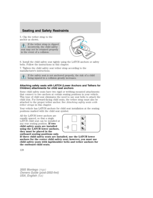
fusesStandard
fusesMaxi
fusesCartridge
maxi
fusesFuse link
cartridge
5A Tan Tan — — —
7.5A Brown Brown — — —
10A Red Red — — —
15A Blue Blue — — —
20A Yellow Yellow Yellow Blue Blue
25A Natural Natural — — —
30A Green Green Green Pink Pink
40A — — Orange Green Green
50A — — Red Red Red
60A — — Blue Yellow Yellow
80A — — Natural Black Black
Passenger compartment fuse panel/Smart Junction Box (SJB)
The fuse panel is located under the instrument panel to the left of the
steering wheel.
The fuses are coded as follows.
2005 Montego(mgo)
Owners Guide (post-2002-fmt)
USA_English(fus)
Roadside Emergencies
185
Page 186 of 264

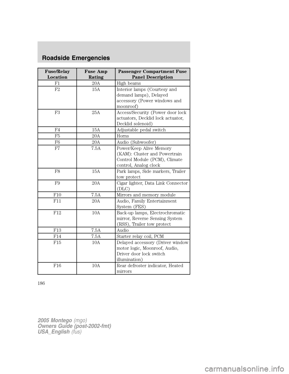
Fuse/Relay
LocationFuse Amp
RatingPassenger Compartment Fuse
Panel Description
F1 20A High beams
F2 15A Interior lamps (Courtesy and
demand lamps), Delayed
accessory (Power windows and
moonroof)
F3 25A Access/Security (Power door lock
actuators, Decklid lock actuator,
Decklid solenoid)
F4 15A Adjustable pedal switch
F5 20A Horns
F6 20A Audio (Subwoofer)
F7 7.5A Power/Keep Alive Memory
(KAM): Cluster and Powertrain
Control Module (PCM), Climate
control, Analog clock
F8 15A Park lamps, Side markers, Trailer
tow protect
F9 20A Cigar lighter, Data Link Connector
(DLC)
F10 7.5A Mirrors and memory module
F11 20A Audio, Family Entertainment
System (FES)
F12 10A Back-up lamps, Electrochromatic
mirror, Reverse Sensing System
(RSS), Trailer tow protect
F13 7.5A Audio
F14 7.5A Starter relay coil, PCM
F15 10A Delayed accessory (Driver window
motor logic, Moonroof, Audio,
Driver door lock switch
illumination)
F16 10A Rear defroster indicator, Heated
mirrors
2005 Montego(mgo)
Owners Guide (post-2002-fmt)
USA_English(fus)
Roadside Emergencies
186
Page 187 of 264

Fuse/Relay
LocationFuse Amp
RatingPassenger Compartment Fuse
Panel Description
F17 30A Rear defroster
F18 10A PCM relay coil, Shifter Brake-Shift
Interlock (BSI), Passive
Anti-Theft System (PATS)
module, Fuel relay coil, Brake
lamps, Center High-Mounted Stop
Lamp (CHMSL)
F19 10A Anti-lock Brake System
(ABS)/Traction control module,
All Wheel Drive (AWD) module,
RSS, Heated seat modules
F20 7.5A Cluster, Climate control
F21 7.5A Restraint Control Module (RCM)
F22 7.5A Electrochromatic mirror, Compass
module
F23 7.5A Wiper relay coil, Blower relay coil,
Cluster logic
F24 7.5A Occupant Classification Sensor
(OCS), Passenger Air bag
Deactivation (PAD)
C1 30A Circuit
breakerDelayed accessory (Front
passenger window, Rear passenger
windows [via window switch],
Window switch illumination,
Backlighting
Power distribution box
The power distribution box is located in the engine compartment. The
power distribution box contains high-current fuses that protect your
vehicle’s main electrical systems from overloads.
Always disconnect the battery before servicing high current
fuses.
2005 Montego(mgo)
Owners Guide (post-2002-fmt)
USA_English(fus)
Roadside Emergencies
187
Page 188 of 264
To reduce risk of electrical shock, always replace the cover to
the Power Distribution Box before reconnecting the battery or
refilling fluid reservoirs.
If the battery has been disconnected and reconnected, refer to the
Batterysection of theMaintenance and Specificationschapter.
The high-current fuses are coded as follows:
Fuse/Relay
LocationFuse Amp
RatingPower Distribution Box
Description
1 80A* SJB, SJB fuses 1, 2, 3, 4, 5, 8 and
12
2 — Not used
3 — Not used
4 50A* Wiper RUN/ACC relay to PDB,
PDB fuses 37 and 38
5 — Not used
6 20A* Moonroof
7 — Not used
8 60A* Engine cooling fan
9 — Not used
2005 Montego(mgo)
Owners Guide (post-2002-fmt)
USA_English(fus)
Roadside Emergencies
188
Page 189 of 264
Fuse/Relay
LocationFuse Amp
RatingPower Distribution Box
Description
10 40A* Anti-lock Brake System (ABS)
(Motor)
11 30A* Starter
12 30A* Powertrain Control Module (PCM)
relay
13 20A* ABS (Valves)
14 — Not used
15 — Not used
16 15A** Traction Control Module (TCM)
17 20A** Power point (Console)
18 10A** Alternator
19 40A* Logic feed to SJB, SJB solid state
devices
20 20A* Right-hand HID low beam
headlamp
21 40A* Rear defroster
22 30A* Power seat motors (passenger)
23 30A* Heated seat modules
24 15A** Fog lamps
25 10A** A/C clutch relay, A/C compressor
clutch
26 — Not used
27 — Not used
28 15A** Fuel relay (Fuel pump driver
module, Fuel pump)
29 80A* SJB power, SJB (Circuit breaker,
Fuses 6, 7, 9, 10, 11 and 15)
30 30A* Driver window motor
31 20A* Left-hand HID low beam
headlamp
32 — Not used
2005 Montego(mgo)
Owners Guide (post-2002-fmt)
USA_English(fus)
Roadside Emergencies
189
Page 190 of 264
Fuse/Relay
LocationFuse Amp
RatingPower Distribution Box
Description
33 30A* Driver seat motors, Memory
module
34 30A* Ignition switch (to SJB)
35 — Not used
36 40A* Front A/C blower motor
37 30A** Front wiper, Front washer
38 5A** Heated Positive Crankcase
Ventilation (PCV) valve
39 — Not used
40 10A** TCM, EVMV, Canister vent, ESM,
Exhaust Gas Oxygen heaters, A/C
clutch
41 15A** PCM, Injectors, Ignition coils,
Mass Air Flow (MAF) sensor
42 — Not used
43 — Not used
44 — Not used
45 — Not used
46 — Not used
47 — Not used
48
1 2ISO relay Fog lamps
49 — Not used
50 — Not used
51
1 2ISO relay A/C clutch
52 — Not used
53
1 2ISO relay Fuel pump driver module, Fuel
pump
54 — Not used
55 Full ISO relay PCM relay, PDB fuses 40 and 41
56 Full ISO relay Starter motor solenoid
57 Full ISO relay Front A/C blower motor
2005 Montego(mgo)
Owners Guide (post-2002-fmt)
USA_English(fus)
Roadside Emergencies
190
Page 191 of 264

Fuse/Relay
LocationFuse Amp
RatingPower Distribution Box
Description
58 High current
relayWipers
59 — Not used
60 1A Diode PCM
61 1A Diode PCM
* Cartridge Fuses ** Mini Fuses
JUMP STARTING YOUR VEHICLE
The gases around the battery can explode if exposed to flames,
sparks, or lit cigarettes. An explosion could result in injury or
vehicle damage.
Batteries contain sulfuric acid which can burn skin, eyes and
clothing, if contacted.
Do not attempt to push-start your vehicle. Automatic
transmissions do not have push-start capability; doing so may
damage the catalytic converter.
Preparing your vehicle
When the battery is disconnected or a new battery is installed, the
transmission must relearn its shift strategy. As a result, the transmission
may have firm and/or soft shifts. This operation is considered normal and
will not affect function or durability of the transmission. Over time, the
adaptive learning process will fully update transmission operation.
1.Use only a 12–volt supply to start your vehicle.
2. Do not disconnect the battery of the disabled vehicle as this could
damage the vehicle’s electrical system.
3. Park the booster vehicle close to the hood of the disabled vehicle
making sure the two vehiclesdo nottouch. Set the parking brake on
both vehicles and stay clear of the engine cooling fan and other moving
parts.
4. Check all battery terminals and remove any excessive corrosion before
you attach the battery cables. Ensure that vent caps are tight and level.
5. Turn the heater fan on in both vehicles to protect any electrical
surges. Turn all other accessories off.
2005 Montego(mgo)
Owners Guide (post-2002-fmt)
USA_English(fus)
Roadside Emergencies
191
Page 192 of 264
Connecting the jumper cables
1. Connect the positive (+) jumper cable to the positive (+) terminal of
the discharged battery.
Note:In the illustrations,lightning boltsare used to designate the
assisting (boosting) battery.
2. Connect the other end of the positive (+) cable to the positive (+)
terminal of the assisting battery.
+–+–
+–+–
2005 Montego(mgo)
Owners Guide (post-2002-fmt)
USA_English(fus)
Roadside Emergencies
192