2005 MERCEDES-BENZ SPRINTER fuel filter
[x] Cancel search: fuel filterPage 797 of 1232
(7) Install the right intake manifold support brack-
ets. Tighten the bolts to 14 N´m (124 lbs. in.) (Fig.
63).
(8) Install the lower intake manifold support
bracket. Tighten bolts to 20 N´m (177 lbs. in.) (Fig.
63).
(9) Connect both fuel lines to fuel filter assembly
(Refer to 14 - FUEL SYSTEM/FUEL DELIVERY/
FUEL FILTER - INSTALLATION).
(10) Connect the coolant hose at the connection
junction above the lower intake manifold support
bracket (Fig. 63).
(11) Secure the engine wiring harness and cable
duct to the intake manifold (Fig. 63).
(12) Connect the EGR wiring harness connector
(Fig. 63).
(13) Connect the charge air hose to the intake
manifold (Fig. 63).
(14) Carefully route the engine wiring harness
through and into the passenger compartment and
reconnect.
(15) Install the engine cover.
(16) Fill the cooling system.
(17) Connect the negative battery cable.
(18) Start the engine and inspect for leaks. Care
must be taken to observe the fuel system warnin-
g.(Refer to 14 - FUEL SYSTEM - WARNING).
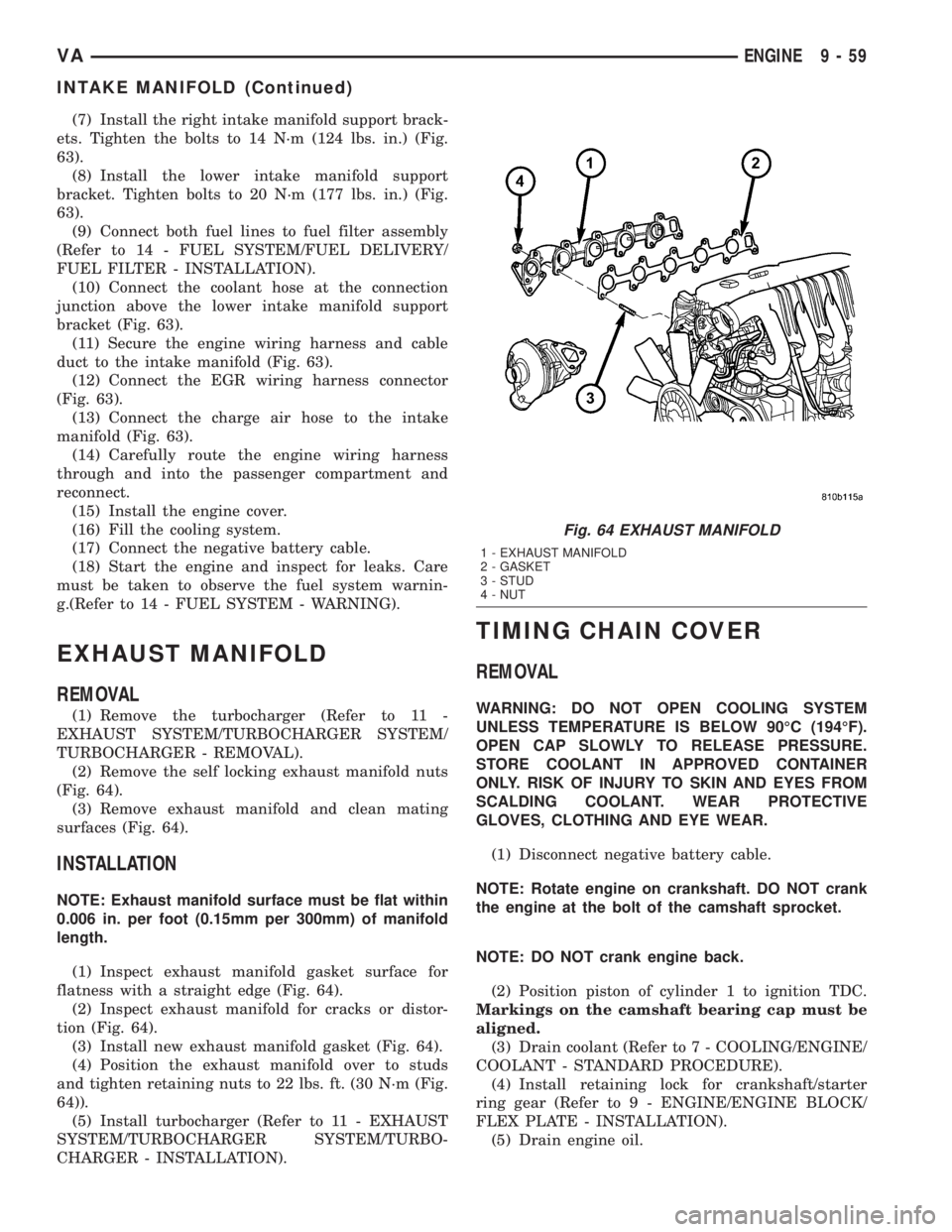
EXHAUST MANIFOLD
REMOVAL
(1) Remove the turbocharger (Refer to 11 -
EXHAUST SYSTEM/TURBOCHARGER SYSTEM/
TURBOCHARGER - REMOVAL).
(2) Remove the self locking exhaust manifold nuts
(Fig. 64).
(3) Remove exhaust manifold and clean mating
surfaces (Fig. 64).
INSTALLATION
NOTE: Exhaust manifold surface must be flat within
0.006 in. per foot (0.15mm per 300mm) of manifold
length.
(1) Inspect exhaust manifold gasket surface for
flatness with a straight edge (Fig. 64).
(2) Inspect exhaust manifold for cracks or distor-
tion (Fig. 64).
(3) Install new exhaust manifold gasket (Fig. 64).
(4) Position the exhaust manifold over to studs
and tighten retaining nuts to 22 lbs. ft. (30 N´m (Fig.
64)).
(5) Install turbocharger (Refer to 11 - EXHAUST
SYSTEM/TURBOCHARGER SYSTEM/TURBO-
CHARGER - INSTALLATION).
TIMING CHAIN COVER
REMOVAL
WARNING: DO NOT OPEN COOLING SYSTEM
UNLESS TEMPERATURE IS BELOW 90ÉC (194ÉF).
OPEN CAP SLOWLY TO RELEASE PRESSURE.
STORE COOLANT IN APPROVED CONTAINER
ONLY. RISK OF INJURY TO SKIN AND EYES FROM
SCALDING COOLANT. WEAR PROTECTIVE
GLOVES, CLOTHING AND EYE WEAR.
(1) Disconnect negative battery cable.
NOTE: Rotate engine on crankshaft. DO NOT crank
the engine at the bolt of the camshaft sprocket.
NOTE: DO NOT crank engine back.
(2) Position piston of cylinder 1 to ignition TDC.
Markings on the camshaft bearing cap must be
aligned.
(3) Drain coolant (Refer to 7 - COOLING/ENGINE/
COOLANT - STANDARD PROCEDURE).
(4) Install retaining lock for crankshaft/starter
ring gear (Refer to 9 - ENGINE/ENGINE BLOCK/
FLEX PLATE - INSTALLATION).
(5) Drain engine oil.
Fig. 64 EXHAUST MANIFOLD
1 - EXHAUST MANIFOLD
2 - GASKET
3 - STUD
4 - NUT
VAENGINE 9 - 59
INTAKE MANIFOLD (Continued)
Page 798 of 1232
(6) Remove the oil filter to allow the oil to flow off
into the oil pan.
(7) Remove the radiator assembly (Refer to 7 -
COOLING/ENGINE/RADIATOR - REMOVAL).
(8) Remove engine cover (Refer to 9 - ENGINE -
REMOVAL).
(9) Remove front cover at cylinder head (Refer to 9
- ENGINE/CYLINDER HEAD - REMOVAL).
(10) Remove accessory drive belt.
(11) Remove the high pressure fuel pump (Refer to
14 - FUEL SYSTEM/FUEL DELIVERY/FUEL PUMP
- REMOVAL).
(12) Remove water pump (Refer to 7 - COOLING/
ENGINE/WATER PUMP - REMOVAL).
(13) Remove accessory drive belt pulley and vibra-
tion damper (Refer to 9 - ENGINE/ENGINE BLOCK/
VIBRATION DAMPER - REMOVAL).
(14) Remove the power steering pump.
NOTE: NO NOT open the air conditioning system.
(15) Unplug AC compressor electrical connector
and unbolt AC compressor. Relocate in lower engine
compartmentwith outopening the system.
(16) Remove the generator with wiring attached
and relocate somewhere in the engine compartment.
(17) Install engine support fixture.
(18) Remove the oil pan.
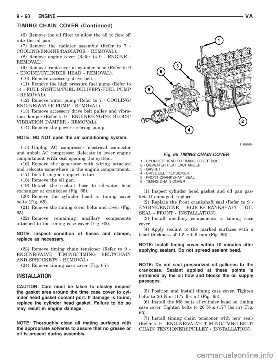
(19) Detach the coolant hose to oil-water heat
exchanger at crankcase (Fig. 65).
(20) Remove the cylinder head to timing cover
bolts (Fig. 65).
(21) Remove the timing cover bolts and cover (Fig.
65).
(22) Remove remaining ancillary components
attached to the timing case cover (Fig. 65).
NOTE: Inspect condition of hoses and clamps,
replace as necessary.
(23) Remove timing chain tensioner (Refer to 9 -
ENGINE/VALVE TIMING/TIMING BELT/CHAIN
AND SPROCKETS - REMOVAL)
(24) Remove timing case cover (Fig. 65).
INSTALLATION
CAUTION: Care must be taken to closley inspect
the gasket area around the time case cover to cyl-
inder head gasket coolant port. If damage is found,
replace the cylinder head gasket. Failure to do so
may result in engine damage.
NOTE: Thoroughly clean all mating surfaces with
the appropriate solvents to assure that no grease or
oil is present during assembly.(1) Inspect cylinder head gasket and oil pan gas-
ket. If damaged, replace.
(2) Replace the front crankshaft seal (Refer to 9 -
ENGINE/ENGINE BLOCK/CRANKSHAFT OIL
SEAL - FRONT - INSTALLATION).
(3) Install ancillary components to timing case
cover.
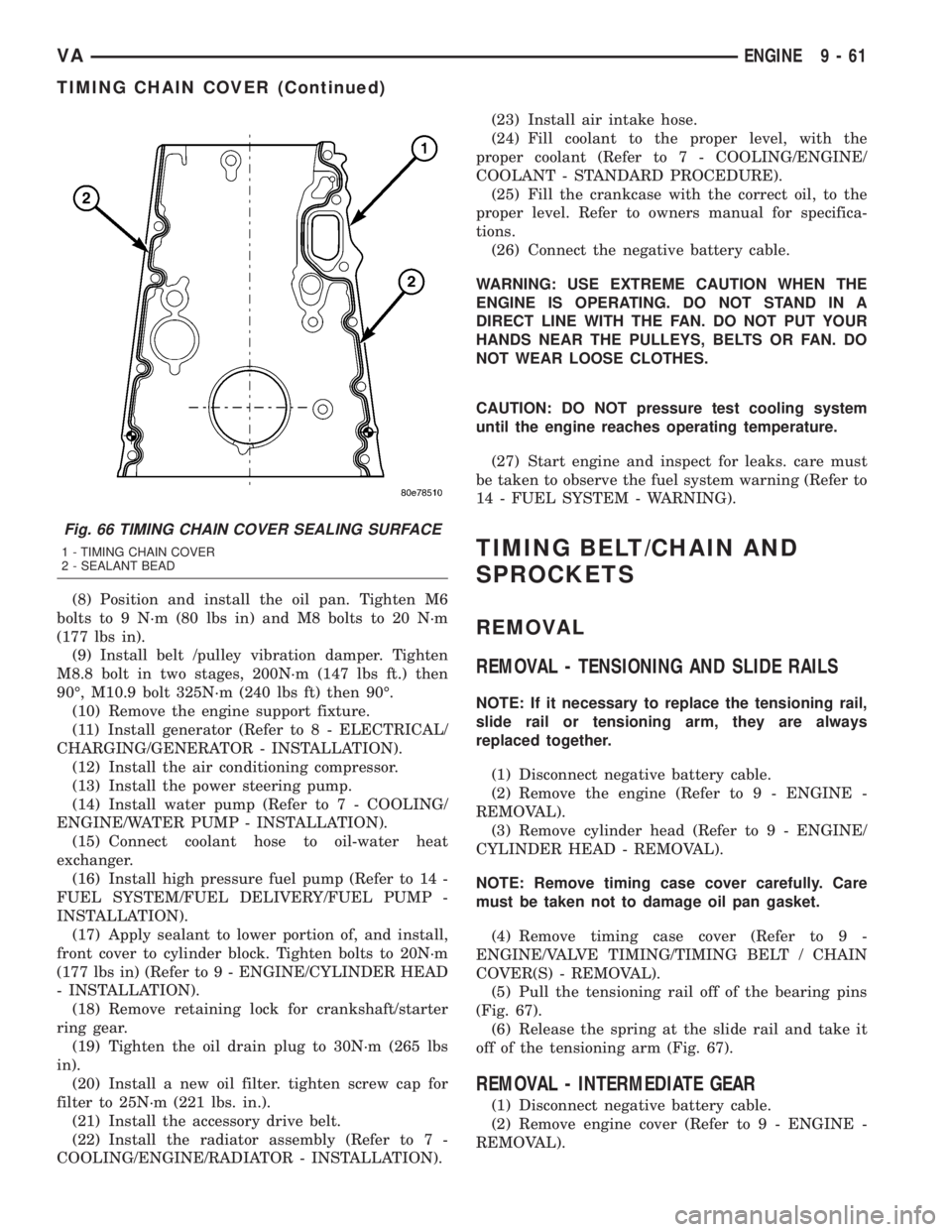
(4) Apply sealant to the marked surfaces with a
bead thickness of 1.5 0.5 mm (Fig. 66).
NOTE: Install timing cover within 10 minutes after
applying sealant. Do not spread sealant bead.
NOTE: Do not seal pressurized oil galleries to the
crankcase. Sealant applied at these points is
entrained by the oil flow and blocks the oil supply
passages.
(5) Position and install timing case cover. Tighten
bolts to 20 N´m (177 lbs in) (Fig. 65).
(6) Install the M8 bolts of cylinder head on timing
case cover. Tighten bolts to 20 N´m (177 lbs in) (Fig.
65).
(7) Install timing chain tensioner with new seal-
(Refer to 9 - ENGINE/VALVE TIMING/TMNG BELT/
CHAIN TENSIONER&PULLEY - INSTALLATION).
Fig. 65 TIMING CHAIN COVER
1 - CYLINDER HEAD TO TIMING COVER BOLT
2 - OIL-WATER HEAT EXCHANGER
3 - GASKET
4 - DRIVE BELT TENSIONER
5 - FRONT CRANKSHAFT SEAL
6 - TIMING CHAIN COVER
9 - 60 ENGINEVA
TIMING CHAIN COVER (Continued)
Page 799 of 1232
(8) Position and install the oil pan. Tighten M6
bolts to 9 N´m (80 lbs in) and M8 bolts to 20 N´m
(177 lbs in).
(9) Install belt /pulley vibration damper. Tighten
M8.8 bolt in two stages, 200N´m (147 lbs ft.) then
90É, M10.9 bolt 325N´m (240 lbs ft) then 90É.
(10) Remove the engine support fixture.
(11) Install generator (Refer to 8 - ELECTRICAL/
CHARGING/GENERATOR - INSTALLATION).
(12) Install the air conditioning compressor.
(13) Install the power steering pump.
(14) Install water pump (Refer to 7 - COOLING/
ENGINE/WATER PUMP - INSTALLATION).
(15) Connect coolant hose to oil-water heat
exchanger.
(16) Install high pressure fuel pump (Refer to 14 -
FUEL SYSTEM/FUEL DELIVERY/FUEL PUMP -
INSTALLATION).
(17) Apply sealant to lower portion of, and install,
front cover to cylinder block. Tighten bolts to 20N´m
(177 lbs in) (Refer to 9 - ENGINE/CYLINDER HEAD
- INSTALLATION).
(18) Remove retaining lock for crankshaft/starter
ring gear.
(19) Tighten the oil drain plug to 30N´m (265 lbs
in).
(20) Install a new oil filter. tighten screw cap for
filter to 25N´m (221 lbs. in.).
(21) Install the accessory drive belt.
(22) Install the radiator assembly (Refer to 7 -
COOLING/ENGINE/RADIATOR - INSTALLATION).(23) Install air intake hose.
(24) Fill coolant to the proper level, with the
proper coolant (Refer to 7 - COOLING/ENGINE/
COOLANT - STANDARD PROCEDURE).
(25) Fill the crankcase with the correct oil, to the
proper level. Refer to owners manual for specifica-
tions.
(26) Connect the negative battery cable.
WARNING: USE EXTREME CAUTION WHEN THE
ENGINE IS OPERATING. DO NOT STAND IN A
DIRECT LINE WITH THE FAN. DO NOT PUT YOUR
HANDS NEAR THE PULLEYS, BELTS OR FAN. DO
NOT WEAR LOOSE CLOTHES.
CAUTION: DO NOT pressure test cooling system
until the engine reaches operating temperature.
(27) Start engine and inspect for leaks. care must
be taken to observe the fuel system warning (Refer to
14 - FUEL SYSTEM - WARNING).
TIMING BELT/CHAIN AND
SPROCKETS
REMOVAL
REMOVAL - TENSIONING AND SLIDE RAILS
NOTE: If it necessary to replace the tensioning rail,
slide rail or tensioning arm, they are always
replaced together.
(1) Disconnect negative battery cable.
(2) Remove the engine (Refer to 9 - ENGINE -
REMOVAL).
(3) Remove cylinder head (Refer to 9 - ENGINE/
CYLINDER HEAD - REMOVAL).
NOTE: Remove timing case cover carefully. Care
must be taken not to damage oil pan gasket.
(4) Remove timing case cover (Refer to 9 -
ENGINE/VALVE TIMING/TIMING BELT / CHAIN
COVER(S) - REMOVAL).
(5) Pull the tensioning rail off of the bearing pins
(Fig. 67).
(6) Release the spring at the slide rail and take it
off of the tensioning arm (Fig. 67).
REMOVAL - INTERMEDIATE GEAR
(1) Disconnect negative battery cable.
(2) Remove engine cover (Refer to 9 - ENGINE -
REMOVAL).
Fig. 66 TIMING CHAIN COVER SEALING SURFACE
1 - TIMING CHAIN COVER
2 - SEALANT BEAD
VAENGINE 9 - 61
TIMING CHAIN COVER (Continued)
Page 829 of 1232
FUEL SYSTEM
TABLE OF CONTENTS
page page
FUEL SYSTEM
WARNING
WARNING - HIGH FUEL SYSTEM
PRESSURE...........................1
WARNING............................1
DIAGNOSIS AND TESTING
DIAGNOSIS AND TESTING - HIGH
PRESSURE FUEL LINES.................1
DIAGNOSIS AND TESTING - AIR IN FUEL
SYSTEM.............................2
STANDARD PROCEDURE
STANDARD PROCEDURES - CLEANING
FUEL SYSTEM COMPONENTS............2STANDARD PROCEDURE -
DISCONNECTING AND CONNECTING
FUEL LINES..........................2
STANDARD PROCEDURES - DRAINING
WATER FROM FUEL FILTER..............2
STANDARD PROCEDURE - LOW
PRESSURE FUEL PUMP TEST............3
FUEL DELIVERY..........................4
FUEL INJECTION........................17
FUEL SYSTEM
WARNING
WARNING - HIGH FUEL SYSTEM PRESSURE
WARNING: HIGH-PRESSURE FUEL LINES DELIVER
FUEL UNDER EXTREME PRESSURE FROM THE
INJECTION PUMP TO THE INJECTORS. THIS
MAYBE AS HIGH AS 1600BAR (23,200PSI). USE
EXTREME CAUTION WHEN INSPECTING FOR HIGH-
PRESSURE FUEL LEAKS. FUEL UNDER THIS
AMOUNT OF PRESSURE CAN PENETRATE SKIN
CAUSING PERSONAL INJURY OR DEATH. INSPECT
HIGH-PRESSURE FUEL LEAKS WITH A SHEET OF
CARDBOARD. WEAR SAFETY GOGGLES AND ADE-
QUATE PROTECTIVE CLOTHING WHEN SERVICING
FUEL SYSTEM.
WARNING
WARNING: UNDER NO CIRCUMSTANCES SHOULD
GASOLINE BE MIXED WITH DIESEL FUEL (NOT
EVEN DURING WINTER). THE HIGH PRESSURE
PUMP IS LUBRICATED BY DIESEL FUEL. IMMEDI-
ATE FUEL SYSTEM DAMAGE MAY OCCUR CAUS-
ING REPLACEMENT AND FLUSHING OF THE
COMPLETE DIESEL FUEL SYSTEM. HIGH PRES-
SURE PUMP SEIZURE WILL CAUSE METAL PARTI-
CLES TO SPREAD THROUGH OUT THE FUEL
CIRCUIT. ALL CDI FUEL SYSTEM COMPONENTS
CONNECTED TO THE FUEL CIRCUIT WILL HAVE TO
BE EXCHANGED AND THE LINES FLUSHED.
DIAGNOSIS AND TESTING
DIAGNOSIS AND TESTING - HIGH PRESSURE
FUEL LINES
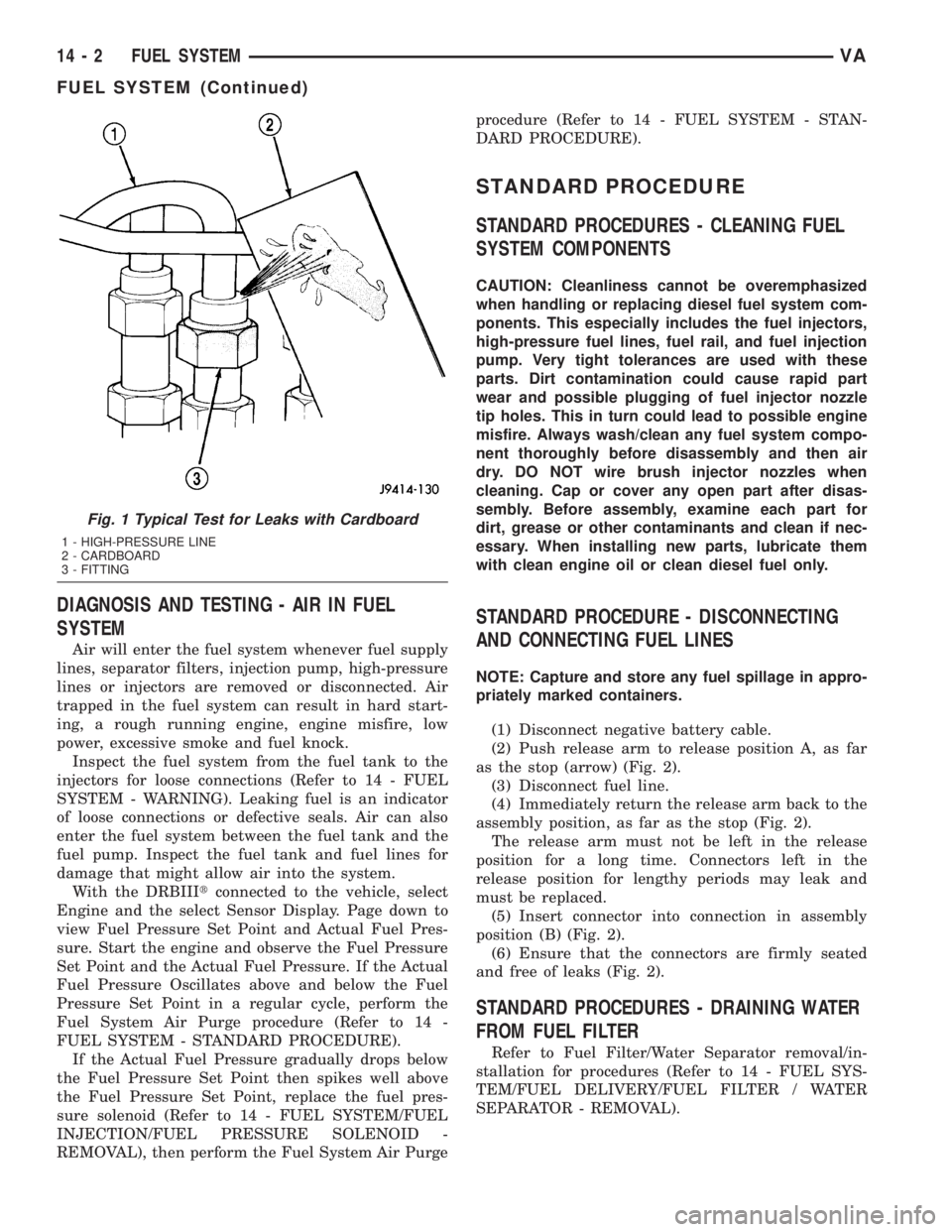
(Refer to 14 - FUEL SYSTEM - WARNING). High-
pressure fuel line leaks can cause starting problems
and poor engine performance.
WARNING: DUE TO EXTREME FUEL PRESSURES,
USE EXTREME CAUTION WHEN INSPECTING FOR
HIGH-PRESSURE FUEL LEAKS. DO NOT GET YOUR
HAND NEAR A SUSPECTED LEAK. INSPECT FOR
HIGH-PRESSURE FUEL LEAKS WITH A SHEET OF
CARDBOARD. HIGH FUEL INJECTION PRESSURE
CAN CAUSE PERSONAL INJURY IF CONTACT IS
MADE WITH THE SKIN.
Start the engine. Move the cardboard over the
high-pressure fuel lines and check for fuel spray onto
the cardboard (Fig. 1). If a high-pressure line connec-
tion is leaking, tighten the connection and perform
the Fuel System Air Purge procedure (Refer to 14 -
FUEL SYSTEM - STANDARD PROCEDURE).
Replace damaged, restricted or leaking high-pressure
fuel lines with the correct replacement line.
CAUTION: The high-pressure fuel lines cannot con-
tact each other or other components. Do not
attempt to weld high-pressure fuel lines or to repair
lines that are damaged. Only use the recommended
lines when replacement of high-pressure fuel line is
necessary.
VAFUEL SYSTEM 14 - 1
Page 830 of 1232
DIAGNOSIS AND TESTING - AIR IN FUEL
SYSTEM
Air will enter the fuel system whenever fuel supply
lines, separator filters, injection pump, high-pressure
lines or injectors are removed or disconnected. Air
trapped in the fuel system can result in hard start-
ing, a rough running engine, engine misfire, low
power, excessive smoke and fuel knock.
Inspect the fuel system from the fuel tank to the
injectors for loose connections (Refer to 14 - FUEL
SYSTEM - WARNING). Leaking fuel is an indicator
of loose connections or defective seals. Air can also
enter the fuel system between the fuel tank and the
fuel pump. Inspect the fuel tank and fuel lines for
damage that might allow air into the system.
With the DRBIIItconnected to the vehicle, select
Engine and the select Sensor Display. Page down to
view Fuel Pressure Set Point and Actual Fuel Pres-
sure. Start the engine and observe the Fuel Pressure
Set Point and the Actual Fuel Pressure. If the Actual
Fuel Pressure Oscillates above and below the Fuel
Pressure Set Point in a regular cycle, perform the
Fuel System Air Purge procedure (Refer to 14 -
FUEL SYSTEM - STANDARD PROCEDURE).
If the Actual Fuel Pressure gradually drops below
the Fuel Pressure Set Point then spikes well above
the Fuel Pressure Set Point, replace the fuel pres-
sure solenoid (Refer to 14 - FUEL SYSTEM/FUEL
INJECTION/FUEL PRESSURE SOLENOID -
REMOVAL), then perform the Fuel System Air Purgeprocedure (Refer to 14 - FUEL SYSTEM - STAN-
DARD PROCEDURE).
STANDARD PROCEDURE
STANDARD PROCEDURES - CLEANING FUEL
SYSTEM COMPONENTS
CAUTION: Cleanliness cannot be overemphasized
when handling or replacing diesel fuel system com-
ponents. This especially includes the fuel injectors,
high-pressure fuel lines, fuel rail, and fuel injection
pump. Very tight tolerances are used with these
parts. Dirt contamination could cause rapid part
wear and possible plugging of fuel injector nozzle
tip holes. This in turn could lead to possible engine
misfire. Always wash/clean any fuel system compo-
nent thoroughly before disassembly and then air
dry. DO NOT wire brush injector nozzles when
cleaning. Cap or cover any open part after disas-
sembly. Before assembly, examine each part for
dirt, grease or other contaminants and clean if nec-
essary. When installing new parts, lubricate them
with clean engine oil or clean diesel fuel only.
STANDARD PROCEDURE - DISCONNECTING
AND CONNECTING FUEL LINES
NOTE: Capture and store any fuel spillage in appro-
priately marked containers.
(1) Disconnect negative battery cable.
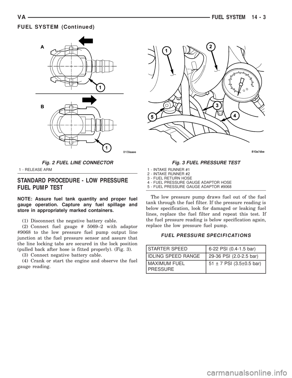
(2) Push release arm to release position A, as far
as the stop (arrow) (Fig. 2).
(3) Disconnect fuel line.
(4) Immediately return the release arm back to the
assembly position, as far as the stop (Fig. 2).
The release arm must not be left in the release
position for a long time. Connectors left in the
release position for lengthy periods may leak and
must be replaced.
(5) Insert connector into connection in assembly
position (B) (Fig. 2).
(6) Ensure that the connectors are firmly seated
and free of leaks (Fig. 2).
STANDARD PROCEDURES - DRAINING WATER
FROM FUEL FILTER
Refer to Fuel Filter/Water Separator removal/in-
stallation for procedures (Refer to 14 - FUEL SYS-
TEM/FUEL DELIVERY/FUEL FILTER / WATER
SEPARATOR - REMOVAL).
Fig. 1 Typical Test for Leaks with Cardboard
1 - HIGH-PRESSURE LINE
2 - CARDBOARD
3 - FITTING
14 - 2 FUEL SYSTEMVA
FUEL SYSTEM (Continued)
Page 831 of 1232
STANDARD PROCEDURE - LOW PRESSURE
FUEL PUMP TEST
NOTE: Assure fuel tank quantity and proper fuel
gauge operation. Capture any fuel spillage and
store in appropriately marked containers.
(1) Disconnect the negative battery cable.
(2) Connect fuel gauge # 5069±2 with adaptor
#9068 to the low pressure fuel pump output line
junction at the fuel pressure sensor and assure that
the line locking tabs are secured in the lock position
(pulled back after hose is fitted properly). (Fig. 3).
(3) Connect negative battery cable.
(4) Crank or start the engine and observe the fuel
gauge reading.The low pressure pump draws fuel out of the fuel
tank through the fuel filter. If the pressure reading is
below specification, look for damaged or leaking fuel
lines, replace the fuel filter and repeat this test. If
the fuel pressure reading is below specification again,
replace the low pressure fuel pump.
FUEL PRESSURE SPECIFICATIONS
STARTER SPEED 6-22 PSI (0.4-1.5 bar)
IDLING SPEED RANGE 29-36 PSI (2.0-2.5 bar)
MAXIMUM FUEL
PRESSURE51 7 PSI (3.5 0.5 bar)
Fig. 2 FUEL LINE CONNECTOR
1 - RELEASE ARM
Fig. 3 FUEL PRESSURE TEST
1 - INTAKE RUNNER #1
2 - INTAKE RUNNER #2
3 - FUEL RETURN HOSE
4 - FUEL PRESSURE GAUGE ADAPTOR HOSE
5 - FUEL PRESSURE GAUGE ADAPTOR #9068
VAFUEL SYSTEM 14 - 3
FUEL SYSTEM (Continued)
Page 832 of 1232
FUEL DELIVERY
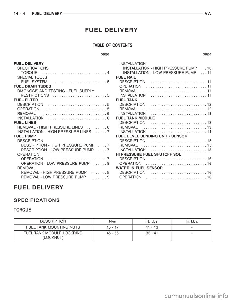
TABLE OF CONTENTS
page page
FUEL DELIVERY
SPECIFICATIONS
TORQUE.............................4
SPECIAL TOOLS
FUEL SYSTEM........................5
FUEL DRAIN TUBES
DIAGNOSIS AND TESTING - FUEL SUPPLY
RESTRICTIONS........................5
FUEL FILTER
DESCRIPTION..........................5
OPERATION............................5
REMOVAL.............................5
INSTALLATION..........................6
FUEL LINES
REMOVAL - HIGH PRESSURE LINES.........6
INSTALLATION - HIGH PRESSURE LINES.....7
FUEL PUMP
DESCRIPTION
DESCRIPTION - HIGH PRESSURE PUMP....7
DESCRIPTION - LOW PRESSURE PUMP....7
OPERATION
OPERATION..........................7
OPERATION - LOW PRESSURE PUMP......8
REMOVAL
REMOVAL - HIGH PRESSURE PUMP.......8
REMOVAL - LOW PRESSURE PUMP.......9INSTALLATION
INSTALLATION - HIGH PRESSURE PUMP . . 10
INSTALLATION - LOW PRESSURE PUMP . . . 11
FUEL RAIL
DESCRIPTION.........................11
OPERATION...........................11
REMOVAL.............................11
INSTALLATION.........................11
FUEL TANK
DESCRIPTION.........................12
REMOVAL.............................12
INSTALLATION.........................13
FUEL TANK MODULE
DESCRIPTION.........................13
REMOVAL.............................13
INSTALLATION.........................14
FUEL LEVEL SENDING UNIT / SENSOR
DESCRIPTION.........................15
REMOVAL.............................15
INSTALLATION.........................15
HI PRESSURE FUEL SHUTOFF SOL
DESCRIPTION.........................16
OPERATION...........................16
WATER IN FUEL SENSOR
DESCRIPTION.........................16
OPERATION...........................16
FUEL DELIVERY
SPECIFICATIONS
TORQUE
DESCRIPTION N´m Ft. Lbs. In. Lbs.
FUEL TANK MOUNTING NUTS 15 - 17 11 - 13 -
FUEL TANK MODULE LOCKRING
(LOCKNUT)45-55 33-41 -
14 - 4 FUEL DELIVERYVA
Page 833 of 1232
SPECIAL TOOLS
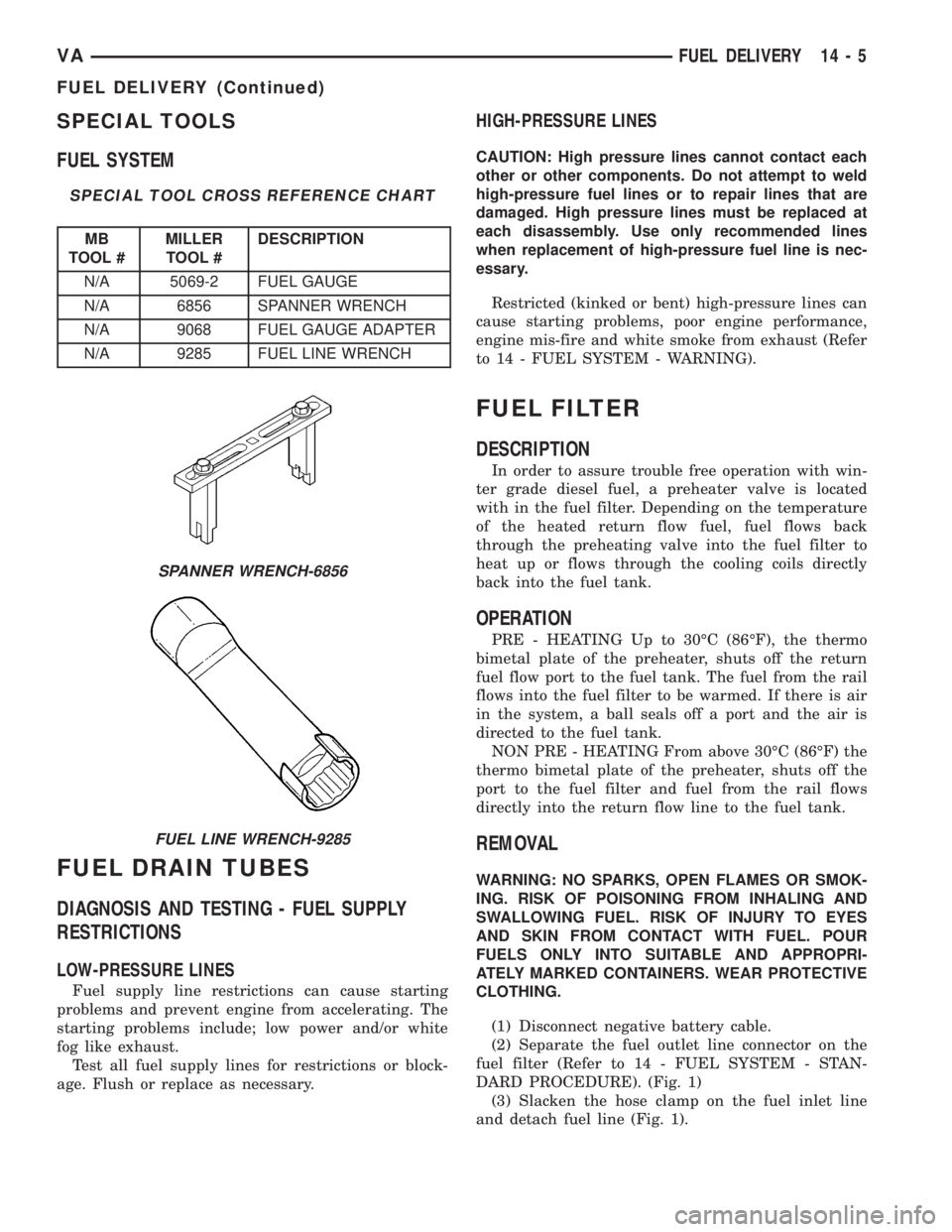
FUEL SYSTEM
SPECIAL TOOL CROSS REFERENCE CHART
MB
TOOL #MILLER
TOOL #DESCRIPTION
N/A 5069-2 FUEL GAUGE
N/A 6856 SPANNER WRENCH
N/A 9068 FUEL GAUGE ADAPTER
N/A 9285 FUEL LINE WRENCH
FUEL DRAIN TUBES
DIAGNOSIS AND TESTING - FUEL SUPPLY
RESTRICTIONS
LOW-PRESSURE LINES
Fuel supply line restrictions can cause starting
problems and prevent engine from accelerating. The
starting problems include; low power and/or white
fog like exhaust.
Test all fuel supply lines for restrictions or block-
age. Flush or replace as necessary.
HIGH-PRESSURE LINES
CAUTION: High pressure lines cannot contact each
other or other components. Do not attempt to weld
high-pressure fuel lines or to repair lines that are
damaged. High pressure lines must be replaced at
each disassembly. Use only recommended lines
when replacement of high-pressure fuel line is nec-
essary.
Restricted (kinked or bent) high-pressure lines can
cause starting problems, poor engine performance,
engine mis-fire and white smoke from exhaust (Refer
to 14 - FUEL SYSTEM - WARNING).
FUEL FILTER
DESCRIPTION
In order to assure trouble free operation with win-
ter grade diesel fuel, a preheater valve is located
with in the fuel filter. Depending on the temperature
of the heated return flow fuel, fuel flows back
through the preheating valve into the fuel filter to
heat up or flows through the cooling coils directly
back into the fuel tank.
OPERATION
PRE - HEATING Up to 30ÉC (86ÉF), the thermo
bimetal plate of the preheater, shuts off the return
fuel flow port to the fuel tank. The fuel from the rail
flows into the fuel filter to be warmed. If there is air
in the system, a ball seals off a port and the air is
directed to the fuel tank.
NON PRE - HEATING From above 30ÉC (86ÉF) the
thermo bimetal plate of the preheater, shuts off the
port to the fuel filter and fuel from the rail flows
directly into the return flow line to the fuel tank.
REMOVAL
WARNING: NO SPARKS, OPEN FLAMES OR SMOK-
ING. RISK OF POISONING FROM INHALING AND
SWALLOWING FUEL. RISK OF INJURY TO EYES
AND SKIN FROM CONTACT WITH FUEL. POUR
FUELS ONLY INTO SUITABLE AND APPROPRI-
ATELY MARKED CONTAINERS. WEAR PROTECTIVE
CLOTHING.
(1) Disconnect negative battery cable.
(2) Separate the fuel outlet line connector on the
fuel filter (Refer to 14 - FUEL SYSTEM - STAN-
DARD PROCEDURE). (Fig. 1)
(3) Slacken the hose clamp on the fuel inlet line
and detach fuel line (Fig. 1).
SPANNER WRENCH-6856
FUEL LINE WRENCH-9285
VAFUEL DELIVERY 14 - 5
FUEL DELIVERY (Continued)