Page 403 of 474
.
Your vehicle is equipped with two
batteries:
�
The starter battery
�
The battery for elect")
401 Practical hints
Batteries
�Batteries
For more information on batteries, see
“Battery” (
�page 277).
Your vehicle is equipped with two
batteries:
�
The starter battery
�
The battery for electrical consumers
(consumer battery), located in the
trunk
The starter battery is located on the
right-hand side of the engine compart-
ment.
1Positive terminal
2Negative terminalThe consumer battery is located on the
right-hand side of the trunk.
3Positive terminal
4Negative terminal
!The starter battery, its filler caps, and
the vent tube must always be securely
installed when the vehicle is in opera-
tion.!The consumer battery located in the
trunk is valve-regulated lead acid
(VRLA) battery, also referred to as
“fleece” battery. Such batteries do not
require topping-up of the electrolyte
level. VRLA batteries therefore do not
have cell caps and the battery cover is
non-removable. Do not attempt to
open the consumer battery as other-
wise the battery will be damaged.
Even though VRLA batteries do not
require topping-up of the electrolyte
level and cannot be opened to check
the electrolyte level, the battery condi-
tion must be checked periodically by
performing a battery conductance test.
Refer to Maintenance Booklet for bat-
tery condition testing intervals.
As with any other battery, disconnect
the consumer battery if you do not in-
tend to operate your vehicle for an
extended period of time to prevent bat-
tery discharge. Contact an authorized
Mercedes-Benz Center for further infor-
mation.
Page 405 of 474
.
�
Turn off the engine (
�page 58).
�
T")
403 Practical hints
Batteries
Disconnecting the batteries�
Make sure the gear selector lever is set
to position P.
�
Close the retractable hardtop
(�page 196).
�
Turn off the engine (
�page 58).
�
Turn off all electrical consumers.
�
Remove the SmartKey from the starter
switch.
or
�
Vehicles with KEYLESS-GO*: Open the
driver’s door.
�
Depress the parking brake.
�
Open the trunk.
Warning!
G
The brake system requires electrical power
to operate.
A malfunction in the vehicle’s power supply
or electrical system may impair brake sys-
tem operation and switch it into its emer-
gency operation mode. The same applies if
battery is disconnected. To brake, the driver
must then apply significantly greater brake
pedal pressure and depress the pedal much
further to obtain the expected braking ef-
fect. If necessary, apply full pressure to the
brake pedal. Brakes are only applied to the
front wheels. Stopping distance is in-
creased! Adjust your driving style according-
ly. For more information, see “SBC brake
system” (
�page 85).
Warning!
G
With a disconnected battery�
you will no longer be able to turn the
SmartKey in the starter switch and
pressing the KEYLESS-GO* start/stop
button on the gear selector lever will
have no effect
�
the gear selector lever will remain
locked in positionP
!Always disconnect the batteries in the
order described below, even if you only
want to charge the starter battery, for
example. Otherwise the vehicle’s
electronics can be damaged.
��
Page 406 of 474
.
�
Use")
404 Practical hintsBatteries�
Unhook the luggage cover in the trunk.
�
Remove the trunk floor.
The battery for electrical consumers is
located in the right hand area of the
trunk (
�page 372).
�
Use the 10 mm open-end wrench from
the vehicle tool kit to disconnect the
negative lead from negative
terminal4 of the consumer battery.
�
Open the hood (
�page 270).
�
Use the 10 mm open-end wrench from
the vehicle tool kit to disconnect the
negative lead from negative
terminal2 of the starter battery.
�
Remove the covers from the positive
terminals 1 and 3.
�
Disconnect the positive lead from pos-
itive terminal 3 of the consumer bat-
tery.
�
Disconnect the positive lead from pos-
itive terminal 1 of the starter battery.
Removing the batteries
Removing the consumer battery�
Remove the screws securing the bat-
tery in the trunk.
�
Remove the battery support and
bracket.
�
Take out the battery.
Removing the starter battery
�
Remove the screws securing the start-
er battery in the engine compartment.
�
Lift the retaining bracket.
�
Remove the battery.
Charging and reinstalling batteries�
Charge batteries in accordance with
the instructions of the battery charger
manufacturer.
�
Reinstall the charged batteries. Follow
the previously described steps in re-
verse order.Warning!
G
Never charge a battery while still installed in
the vehicle. Gases may escape during charg-
ing and cause explosions that may result in
paint damage, corrosion or personal injury.
��
Page 407 of 474
405 Practical hints
Batteries
Reconnecting the batteries�
Turn off all electrical consumers.
�
Install starter battery in the designated
location in the engine compartment.
�
Install consumer battery in the desig-
nated location in the trunk.
�
Attach supports and brackets.
�
Tighten support and bracket screws.
�
Connect positive lead 3 of the con-
sumer battery and positive lead 1 of
the starter battery and fasten covers.
�
Connect negative lead 2 of the starter
battery.
�
Connect negative lead 4 of the con-
sumer battery.
�
Reinstall the trunk floor.
�
Rehook trunk luggage cover into hold-
ers.
!Always connect the batteries in the
order described below. Otherwise the
vehicle’s electronics can be damaged.!Never invert the terminal connections!
iThe following procedures must be car-
ried out following any interruption of
battery power (e.g. due to reconnec-
tion):�
Resynchronize the ESP
(�page 341).
�
Resynchronize side windows
(�page 195).
Page 413 of 474
411 Practical hints
Towing the vehicle
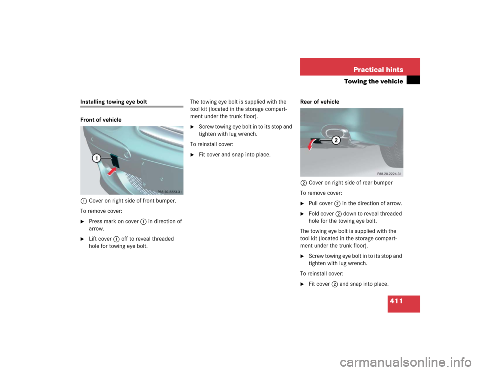
Installing towing eye bolt
Front of vehicle
1Cover on right side of front bumper.
To remove cover:�
Press mark on cover 1 in direction of
arrow.
�
Lift cover1off to reveal threaded
hole for towing eye bolt.The towing eye bolt is supplied with the
tool kit (located in the storage compart-
ment under the trunk floor).
�
Screw towing eye bolt in to its stop and
tighten with lug wrench.
To reinstall cover:
�
Fit cover and snap into place.Rear of vehicle
2Cover on right side of rear bumper
To remove cover:
�
Pull cover 2 in the direction of arrow.
�
Fold cover 2 down to reveal threaded
hole for the towing eye bolt.
The towing eye bolt is supplied with the
tool kit (located in the storage compart-
ment under the trunk floor).
�
Screw towing eye bolt in to its stop and
tighten with lug wrench.
To reinstall cover:
�
Fit cover 2 and snap into place.
Page 414 of 474

412 Practical hintsFusesThe fuses in your vehicle serve to interrupt
the power supply to electrical device that
are malfunctioning. This helps to prevent
damage to other vehicle electronics.
The following aids are available to help you
replace fuses. They are located in the trunk
with the vehicle tool kit (
�page 372).
�
Fuse chart
The fuse chart explains the fuse alloca-
tion and fuse amperages.
�
Spare fuses
�
Fuse extractor
Main fuse box
The main fuse box is located in the engine
compartment on the driver’s side in front
of the bulkhead (wall separating the engine
and passenger compartment).
1Main fuse box cover
2Unlocking
3Locking
Warning
G
Only use fuses approved for Mercedes-Benz
with the specified amperage for the system
in question. Otherwise, a short circuit could
result and cause a fire.
!Only install fuses that have been tested
and approved by Mercedes-Benz and
that have the specified amperage rat-
ing.
Otherwise, electrical parts or compo-
nents could be damaged.
Never attempt to repair or bridge a
blown fuse. Have the cause determined
and remedied by an authorized
Mercedes-Benz Center.
Page 432 of 474
430 Technical dataWeightsTrunk load max.
220 lb (100 kg)
Page 445 of 474

Feature that uses the engine heat
stored in the coolant to heat the vehi-
cle interior for a short time after the en-
gine has been turned")
443 Technical terms
REST
(Residual Engine Heat Utilization)
Feature that uses the engine heat
stored in the coolant to heat the vehi-
cle interior for a short time after the en-
gine has been turned off.
Retractable hardtop
Hardtop roof that can be opened and
closed at the push of a button and
stored in the trunk.
Roll bar
Occupant protection system which
consists of tubular steel sheathed in
plastic. The roll bar is lowered into the
car body during normal driving condi-
tions and raised automatically. It may
also be manually raised and lowered by
operating a button during critical driv-
ing situations.RON
The Research Octane Number for gaso-
line as determined by a standardized
method. It is an indication of a gaso-
line’s ability to resist undesired detona-
tion (knocking). The average of both
the MON (Motor Octane Number) and
RON (Research Octane Number) is
posted at the pump, also known as
ANTI-KNOCK INDEX.
SBC
(S
ensotronic B
rake C
ontrol)
Electronically controlled hydraulic
braking system for increased braking
safety and comfort.
Shift lock
When the vehicle is parked, this lock
prevents the gear selector lever from
being inadvertently moved out of posi-
tion P without SmartKey turned and
brake pedal depressed. SRS
(S
upplemental R
estraint S
ystem)
Seat belts, emergency tensioning de-
vice and airbags. Though independent
systems, they are closely interfaced to
provide effective occupant protection.
Tele Aid System
(Tele
matic A
larm I
dentification on D
e-
mand)
The Tele Aid system consists of three
types of response: automatic and man-
ual emergency, roadside assistance
and information. Tele Aid is initially ac-
tivated by completing a subscriber
agreement and placing an acquain-
tance call.
The Tele Aid system is operational pro-
vided that the vehicle’s battery is
charged, properly connected, not dam-
aged and cellular and GPS coverage is
available.
")