Page 404 of 474

402 Practical hintsFlat tireLowering the vehicle�
Lower vehicle by turning crank coun-
terclockwise until vehicle is resting ful-
ly on its own weight.
�
Remove the jack.
1 - 5 Wheel bolts
�
Tighten the five wheel bolts evenly, fol-
lowing the diagonal sequence illustrat-
ed (1 to 5), until all bolts are tight.
Observe a tightening torque of
110 lb-ft (150 Nm).
�
Before storing the jack in the trunk, it
should be fully collapsed, with handle
folded in.
�
Place the wheel bolt wrench, alignment
bolt and jack back in the vehicle tool kit
in the trunk and close the covering lid.Replacing jack support tube cover
�
Slide tongue of cover under the upper
edge of the tube opening.
�
Applying even pressure, press cover
until it snaps into place. Be careful not
to damage the locking tabs or clamp
the plastic retaining strap.
Warning!
G
Have the tightening torque checked after
changing a wheel. The wheels could come
loose if they are not tightened to a torque of
110 lb-ft (150 Nm).
!You can also screw the faulty wheel
down into the spare wheel well in the
trunk.
Do not activate the tire inflation pres-
sure monitor* until the depressurized
tire is no longer in the vehicle.
Page 405 of 474

403 Practical hints
Battery
�Battery
The battery is located on the right side of
the trunk under the battery cover.
1Battery cover
Warning!
G
Failure to follow these instructions can re-
sult in severe injury or death.
Never lean over batteries while connecting,
you might get injured.
Battery fluid contains sulfuric acid. Do not
allow this fluid to come in contact with eyes,
skin or clothing. In case it does, immediately
flush affected area with water and seek
medical help if necessary.
A battery will also produce hydrogen gas,
which is flammable and explosive. Keep
flames or sparks away from battery, avoid
improper connection of jumper cables,
smoking, etc.
Warning!
G
Do not place metal objects on the battery as
this could result in a short circuit.
Use leak-proof battery only to avoid the risk
of acid burns in the event of an accident.!Never loosen or detach battery termi-
nal clamps while the engine is running
or the SmartKey is in the starter switch.
Otherwise the alternator and other
electronic components could be se-
verely damaged.
Have the battery checked regularly by
an authorized Mercedes-Benz Center.
Refer to Maintenance Booklet for main-
tenance intervals or contact an autho-
rized Mercedes-Benz Center for further
information.
Warning!
G
With a disconnected battery�
you will no longer be able to turn the
SmartKey in the starter switch and
pressing the KEYLESS-GO* start/stop
button (
�page 35) on the gear selector
lever will have no effect
�
the gear selector lever will remain
locked in positionP
Page 406 of 474
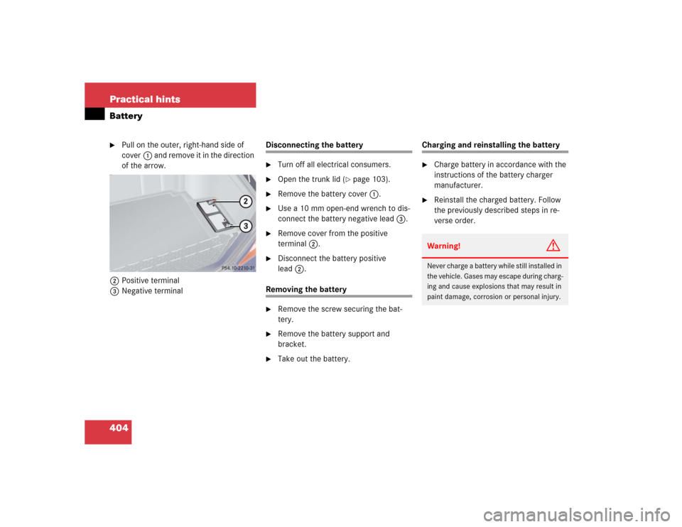
404 Practical hintsBattery�
Pull on the outer, right-hand side of
cover1 and remove it in the direction
of the arrow.
2Positive terminal
3Negative terminal
Disconnecting the battery�
Turn off all electrical consumers.
�
Open the trunk lid (
�page 103).
�
Remove the battery cover1.
�
Use a 10 mm open-end wrench to dis-
connect the battery negative lead3.
�
Remove cover from the positive
terminal2.
�
Disconnect the battery positive
lead2.
Removing the battery�
Remove the screw securing the bat-
tery.
�
Remove the battery support and
bracket.
�
Take out the battery.
Charging and reinstalling the battery�
Charge battery in accordance with the
instructions of the battery charger
manufacturer.
�
Reinstall the charged battery. Follow
the previously described steps in re-
verse order.Warning!
G
Never charge a battery while still installed in
the vehicle. Gases may escape during charg-
ing and cause explosions that may result in
paint damage, corrosion or personal injury.
Page 409 of 474
.
�
Make sure the two vehicles do not
touch.
�
Turn off all electrical con")
407 Practical hints
Jump starting
The battery is located on the right side of
the trunk under the battery cover
(�page 403).
�
Make sure the two vehicles do not
touch.
�
Turn off all electrical consumers.
�
Apply parking brake.
�
Shift gear selector lever to positionP.
�
Open the trunk lid.
�
Remove battery cover (
�page 403).
�
Remove red cover from positive
terminal 1. 1Positive terminal of discharged battery
2Negative terminal of discharged
battery
3Positive terminal of charged battery
4Negative terminal of charged battery
�
Connect positive terminals 1 and3
of the batteries with the jumper cable.
Clamp cable to charged battery3
first.
�
Start engine of the vehicle with the
charged battery and run at idle speed.
�
Connect negative terminals2 and4
of the batteries with the jumper cable.
Clamp cable to charged battery4
first.
�
Start the engine of the disabled vehi-
cle.
Now you can again turn on the electrical
consumers. Do not turn on the lights under
any circumstances.
�
Remove the jumper cables first from
negative terminals2 and4 and then
from positive terminals1 and3.
You can now turn on the lights.
�
Have the battery checked at the near-
est authorized Mercedes-Benz Center.
Warning!
G
Keep flames or sparks away from battery.
Do not smoke.
Observe all safety instructions and precau-
tions when handling automotive batteries
(�page 403).
!Never invert the terminal connections.
Page 412 of 474

410 Practical hintsTowing the vehicle
Installing towing eye bolt
1Cover on right side of front bumper
2Cover on right side of rear bumperRemoving cover
�
Press mark on cover in direction of ar-
row.
�
Lift cover off to reveal threaded hole for
towing eye bolt.
Installing towing eye bolt
�
Take towing eye bolt and wheel wrench
out of trunk (
�page 379).
�
Screw towing eye bolt clockwise into
its stop and tighten with wheel wrench.
Removing towing eye bolt
�
Loosen towing eye bolt counterclock-
wise with wheel wrench.
�
Unscrew towing eye bolt.
�
Store towing eye bolt and wheel
wrench in trunk.
Installing cover
�
Fit cover and snap into place.
!When towing the vehicle with all wheels
on the ground, please note the follow-
ing:
With the automatic central locking acti-
vated and the SmartKey in starter
switch position2, or KEYLESS-GO*
start/stop button (
�page 35) in
position2, the vehicle doors lock if the
le ft f ront whe el as wel l a s t he rig ht rea r
wheel are turning at vehicle speeds of
approximately 9 mph (15 km/h) or
more.
Switch off the tow-away alarm
(
�page 89).
To prevent the vehicle doors from lock-
ing, deactivate the automatic central
locking (
�page 112).
Towing of the vehicle should only be
done using the properly installed tow-
ing eye bolt. Never attach tow cable,
tow rope or tow rod to vehicle chassis,
frame or suspension parts.
Page 413 of 474

and systems controlled by that fus")
411 Practical hintsFuses
�Fuses
Fuses are designed to protect the electri-
cal circuits in your vehicle from a short cir-
cuit. If a fuse is blown, the component(s)
and systems controlled by that fuse will
stop working.
The following aids are available to help you
replace fuses (
�page 411):
�
Fuse chart
�
Spare fuses
�
Special fuse extractorYour vehicle’s electrical fuses are located
in various fuse boxes:
�
In the dashboard on the passenger side
(�page 412)
�
In the rear passenger compartment un-
der the right rear seat (
�page 412)
�
In the engine compartment on the driv-
er’s side (
�page 413)
�
In the engine compartment on the pas-
senger side (
�page 413)
Aids for replacing fuses
Fuse chart
A chart explaining fuse allocation and fuse
amperages can be found in the vehicle tool
kit in the trunk (
�page 379).
Spare fuses
Spare Fuses are found in the vehicle tool
kit in the trunk (�page 379).
Fuse extractor
The fuse extractor is found in the vehicle
tool kit in the trunk (�page 379).
Warning!
G
Only use fuses approved by Mercedes-Benz
and which have the specified amperage. Us-
ing other fuses may cause an overload and
lead to a fire, or cause damage to electrical
components and/or systems.
!Never attempt to repair or bridge a
blown fuse. Have the cause determined
and remedied by an authorized
Mercedes-Benz Center.
Page 430 of 474
428 Technical dataMain dimensions and weightsMain dimensionsWeightsModel
S 430 (220.070)
S 430 (220.170)
S 430 4MATIC (220.183)
S 500 (220.175)
S 500 4MATIC (220.184)
S 55 AMG (220.174)
S 600 (220.176)
Overall vehicle length
198.3 in (5038 mm)
203.1 in (5158 mm)
203.1 in (5158 mm)
203.1 in (5158 mm)
Overall vehicle width
73.0 in (1855 mm)
73.0 in (1855 mm)
73.0 in (1855 mm)
73.0 in (1855 mm)
Overall vehicle height
57.2 in (1454 mm)
57.2 in (1454 mm)
57.2 in (1454 mm)
57.4 in (1457 mm)
Wheelbase
116.7 in (2965 mm)
121.5 in (3085 mm)
121.5 in (3085 mm)
121.5 in (3085 mm)
Track, front
62.0 in (1574 mm)
62.0 in (1574 mm)
62.1 in (1578 mm)
62.0 in (1574 mm)
Track, rear
62.0 in (1574 mm)
62.0 in (1574 mm)
62.1 in (1578 mm)
62.0 in (1574 mm)
Max. roof load
220 lbs (100 kg)
Max. trunk load
220 lbs (100 kg)
Page 445 of 474

443 Index
A
ABC 231, 437
Messages in display 349, 354
Setting vehicle level 230, 232
ABS 25, 80, 437
Malfunction indicator lamp 338
Messages in display 350
Warning lamp 338
Accelerator position, automatic
transmission 180
Accessory weight 322
Accident
In case of 54
Activating
Air conditioner (cooling) 203
Air conditioning 202
Air recirculation mode 199
Anti-theft alarm system 87
Central locking (control system) 168
Charcoal filter 200
Distance warning function* 226
Distronic* 222
Easy-entry/exit feature 170ESP 84
Exterior lamps 132
Exterior rear view mirror parking
position 187
Front and rear fog lamp 132, 134
Hazard warning flasher 136
Headlamps 50
High beams 135
Ignition 34
Ignition with KEYLESS-GO* start/stop
button 36
Immobilizer 57, 86
Limiting opening height of trunk
lid* 169
Manual shift program S 55 AMG 183
Rear window defroster 201
Residual heat 203
Seat heater 125, 126
Seat ventilation* 127
Tow-away alarm 89
Windshield wipers 52Adaptive Damping System (ADS) 229,
437
Adding
Coolant 293
Engine oil 291
Additional turn signals 390
Adjustable air vents, rear passenger
compartment 204
Adjusting 37
Air distribution 196
Air volume 198
Backrest tilt 38
Drive-dynamic seat* 172
Exterior rear view mirror 41
Head restraint height 39
Head restraint tilt 39
Instrument cluster illumination 140
Interior rear view mirror 41
Lumbar support 122
Mirrors 41
Multicontour backrest* 122
Power seat bench* 117
Seat cushion depth 38, 123

S 430 (220.170)
S 430 4MATIC (220.183)
S 500 (220.175)
S 500 4MATIC (220.184)
S 55 AMG (220.174)
S 600 (220.176")