Page 160 of 356

158 Controls in detailDriving systemsWarning indicators
The warning indicators show the distance
between the sensor and the obstacle. The
warning indicators for the front area are lo-
cated above the center air vents in the
dashboard. The warning indicator for the
rear area is located in the rear passenger
compartment lamp.Front area warning indicator1Segments, left side of vehicle
2Segments, right side of vehicle
Each warning indicator has six yellow and
two red segments.The gear selector lever position deter-
mines which warning indicator is activat-
ed.
As soon as the sensors detect an obstacle,
one or more segments light up, depending
on the distance. An intermittent acoustic
warning will also sound as the seventh seg-
ment comes on and a constant acoustic
warning lasting a maximum of
three seconds will sound for the eighth
segment.
Selector lever
position
Warning indicator
D, R, N, P
Front area activated
R
Rear area activated
!If all red segments light up in the warn-
ing indicators, a dirty sensor or a ultra-
sonic signal could be the reason.�
Clean the sensors (
�page 243).
After cleaning the sensors, switch
the ignition on.
Page 161 of 356
159 Controls in detail
Driving systems
Switching Parktronic system on / off
The Parktronic system can switched on or
off manually.
The Parktronic switch is located on the
lower part of the center console.
1Parktronic off
2Indicator lamp
3Parktronic onSwitching off the Parktronic system
�
Press Parktronic switch on upper
part1.
Indicator lamp2 comes on.
Switching on the Parktronic system
�
Press Parktronic switch on lower
part3.
The indicator lamp2 goes out.!If the Parktronic system is malfunction-
ing, all red segments of the warning in-
dicators light up and an additional
warning sounds.
Contact your Mercedes-Benz Light
Truck Center as soon as possible.
iIf you switch the ignition on, the Park-
tronic system will be automatically
switched on.
The rear Parktronic sensors will not au-
tomatically disengage when towing a
trailer. Therefore switch the Parktronic
system off.
Page 162 of 356

160 Controls in detailLoadingLoading instructions
The gross vehicle weight which is the
weight of the vehicle including fuel, tools,
spare wheel, installed accessories, pas-
sengers and luggage / cargo must never
exceed the Gross Vehicle Weight Rating
(GVWR) for your vehicle. In addition, the
load must be distributed in such a way so
that the weight on each axle never exceeds
the Gross Axle Weight Rating (GAWR) for
the front and rear axle. The GVWR and
GAWR for your vehicle are indicated on the
certification label which can be found on
the left door pillar.The handling characteristics of a fully load-
ed vehicle depend greatly on the load dis-
tribution. It is therefore recommended to
load the vehicle according to the illustra-
tions shown, with the heaviest items being
placed towards the front of the vehicle.
Please pay attention to and comply with
the following instructions when loading the
vehicle and transporting cargo:
�
Always place items being carried
against front or rear seat backrests,
and fasten them as securely as possi-
ble.
�
The heaviest portion of the cargo
should always be kept as low as possi-
ble against front or rear seat backrests.
Warning!
G
Always fasten items being carried as secure-
ly as possible using cargo tie-down rings and
fastening materials appropriate for the
weight and size of the load.
In an accident, during hard braking or sud-
den maneuvers, loose items will be thrown
around inside the vehicle, and can cause in-
jury to vehicle occupants unless the items
are securely fastened in the vehicle.
To help avoid personal injury during a colli-
sion or sudden maneuver, always use parti-
tion net when transporting cargo.
Never drive vehicle with the liftgate open.
Deadly carbon monoxide (CO) gases may
enter vehicle interior resulting in uncon-
sciousness and death.
Page 164 of 356

162 Controls in detailLoadingHooks
Four hooks located on the rear compart-
ment trim panels, two on each side.HooksUse the hooks to secure light weight items.
The maximum permissible weight per hook
is 9 lbs (4 kg).
Partition net*Use of the partition net is a particularly im-
portant safety factor when the vehicle is
loaded higher than the top of the seat
backrests with smaller objects.
The partition net can be installed behind
the backrests of the front or rear seats.
Engaging partition net
1Holder
2Mounting hookWarning!
G
Always lock backrest in its upright position
when rear seat bench is occupied by pas-
sengers, or cargo is being carried behind the
seat bench.
To help avoid personal injury from smaller
objects flying in the occupant compartment
during a collision or sudden maneuver, al-
ways use partition net when transporting
cargo.
The partition net cannot prevent the move-
ment of large, heavier objects into the pas-
senger compartment in an accident. Such
items must be properly secured using the
cargo tie-down rings in the cargo compart-
ment floor (
�page 161).
Passenger use of seats behind installed par-
tition net is restricted because of the foot-
well being taken up by the net.
Page 166 of 356
164 Controls in detailLoadingRemoving partition net�
Lift tensioner3 upward to a horizon-
tal position to release tensioning of the
strap.
�
Disengage tie-down hooks1 from
rings2.
�
Remove mounting hooks2
(�page 162) from holder1
(�page 162).
�
Roll up and close the partition net.
�
Store partition net behind rear seat
bench.
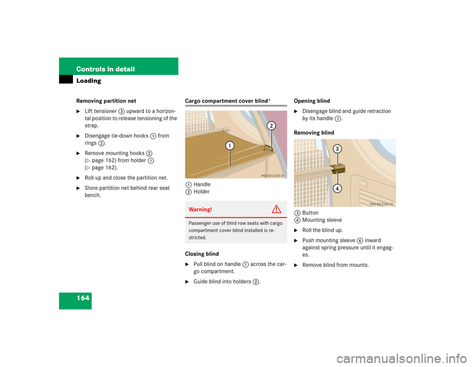
Cargo compartment cover blind*
1Handle
2Holder
Closing blind�
Pull blind on handle1 across the car-
go compartment.
�
Guide blind into holders2.Opening blind
�
Disengage blind and guide retraction
by its handle1.
Removing blind
3Button
4Mounting sleeve
�
Roll the blind up.
�
Push mounting sleeve4 inward
against spring pressure until it engag-
es.
�
Remove blind from mounts.
Warning!
G
Passenger use of third row seats with cargo
compartment cover blind installed is re-
stricted.
Page 168 of 356
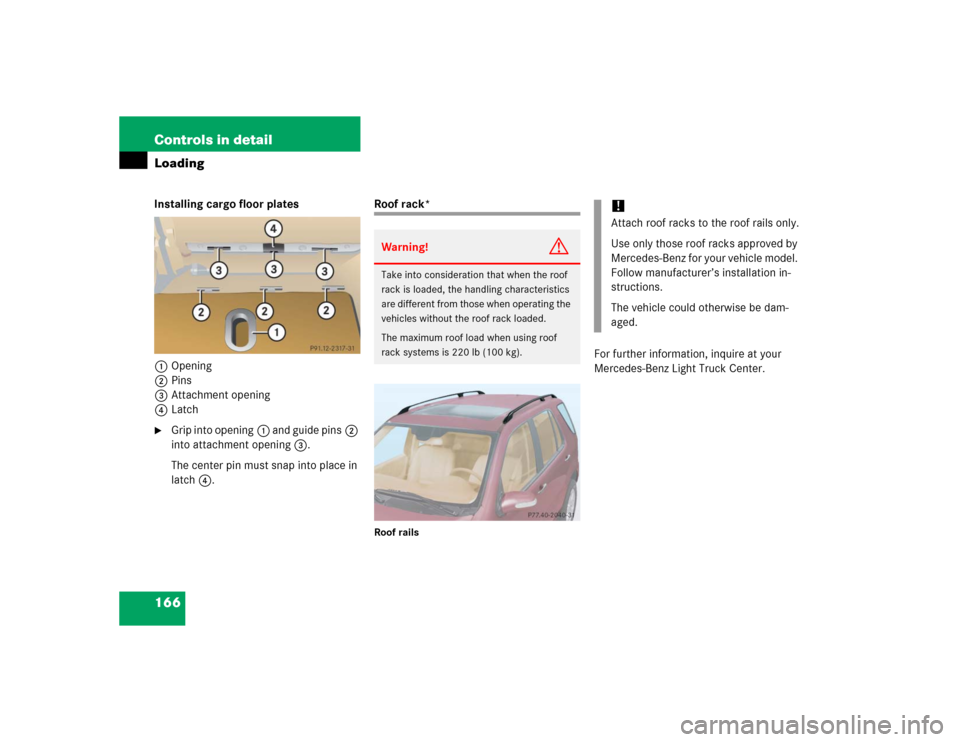
166 Controls in detailLoadingInstalling cargo floor plates
1Opening
2Pins
3Attachment opening
4Latch�
Grip into opening1 and guide pins2
into attachment opening3.
The center pin must snap into place in
latch4.
Roof rack*Roof rails
For further information, inquire at your
Mercedes-Benz Light Truck Center.
Warning!
G
Take into consideration that when the roof
rack is loaded, the handling characteristics
are different from those when operating the
vehicles without the roof rack loaded.
The maximum roof load when using roof
rack systems is 220 lb (100 kg).
!Attach roof racks to the roof rails only.
Use only those roof racks approved by
Mercedes-Benz for your vehicle model.
Follow manufacturer’s installation in-
structions.
The vehicle could otherwise be dam-
aged.
Page 169 of 356

167 Controls in detail
Useful features
�Useful features
Storage compartments Glove box
1Glove box lid release
2Glove box lid
Opening the glove box
�
Grab in recess and pull lid release1.
The glove box lid2 opens downward.
Closing the glove box
�
Push glove box lid up to close.Storage compartment under front
passenger seat*
The storage compartment is lockable with
its separate key.
1Lock cylinder
2Handle
Locking and unlocking the storage com-
partment
�
Turn the key clockwise.
The storage compartment is locked.
�
Turn the key counterclockwise.
The storage compartment is unlocked.
Warning!
G
To help avoid personal injury during a colli-
sion or sudden maneuver, exercise care
when stowing objects in the vehicle. Put lug-
gage or cargo in the cargo compartment if
possible. Do not pile luggage or cargo higher
than the seat backs.
Always use partition net when transporting
cargo. Partition net cannot secure hard or
heavy objects.
Parcel nets cannot secure hard or heavy ob-
jects.
Keep compartment lids closed. This will help
to prevent stored objects from being thrown
about and injuring vehicle occupants during
an accident.
iThe opened glove box is illuminated
with the key in steering lock position1
(�page 33).
Page 171 of 356
169 Controls in detail
Useful features
Opening the storage compartment in
front of armrest�
Slide the cover3 rearward.
The storage compartment below con-
tains a cup holder (
�page 170).
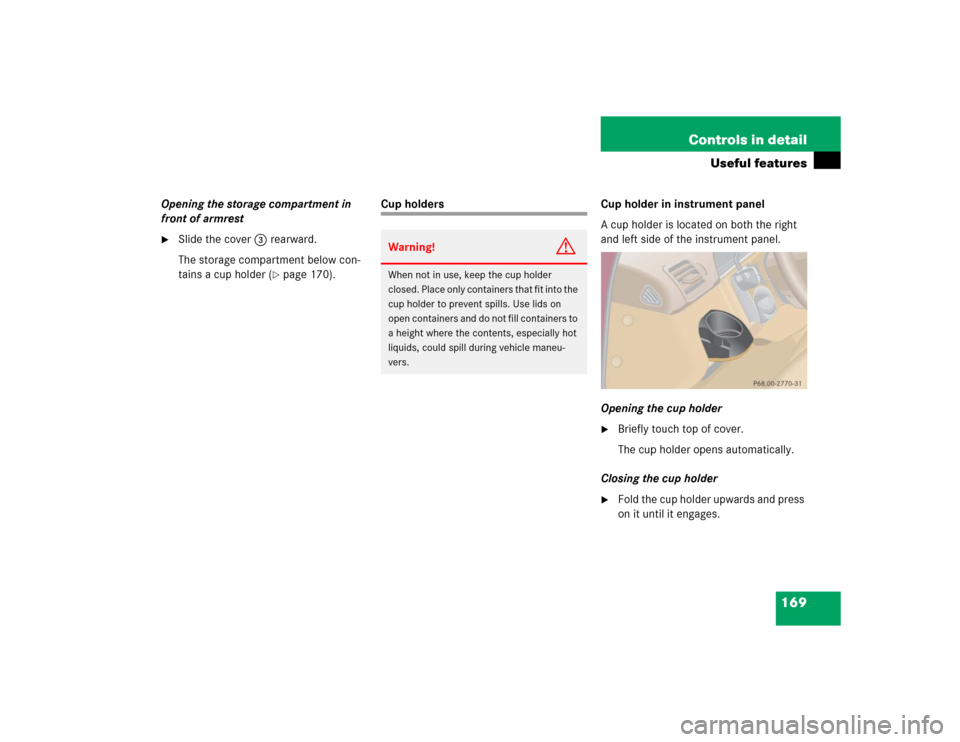
Cup holders Cup holder in instrument panel
A cup holder is located on both the right
and left side of the instrument panel.
Opening the cup holder
�
Briefly touch top of cover.
The cup holder opens automatically.
Closing the cup holder
�
Fold the cup holder upwards and press
on it until it engages.
Warning!
G
When not in use, keep the cup holder
closed. Place only containers that fit into the
cup holder to prevent spills. Use lids on
open containers and do not fill containers to
a height where the contents, especially hot
liquids, could spill during vehicle maneu-
vers.