Page 346 of 416

346 Practical hintsFlat tirePreparing the vehicle�
Park the vehicle as far as possible from
moving traffic on a hard surface.
�
Turn on the hazard warning flashers.
�
Engage the steering wheel lock in the
straight ahead position and set the
parking brake.
�
Move the gear selector lever toP.
�
Have any passenger exit the vehicle at
a safe distance from the roadway.
�
Remove the vehicle tool kit
(�page 321) and the jack
(�page 322).
�
Remove the spare wheel from the
spare wheel mounting bracket
(�page 323).Information on spare wheel
When you replace the vehicle’s tires, you
can use the spare wheel as a regular wheel
if:
�
it is not more than six years old
�
rim and tire are the same model as the
regular wheels
Warning!
G
For your safety, remove spare wheel from
the spare wheel mounting bracket before
undertaking any further steps.
Warning!
G
If the spare tire is more than six years old or
is not the same model as the regular tires,
have the spare tire replaced with a new tire
at the nearest Mercedes-Benz Light Truck
Center.
Never operate the vehicle with more than
one spare tire.
Warning!
G
G55AMG:
Vehicles with different tire dimensions on
the front and rear axle: rim and tire size of
spare wheel and normal wheel differ.
Handling will be adversely affected when the
spare wheel is used.
Do not exceed the maximum speed of
50 mph (80 km/h).
Page 347 of 416
.
Lifting the vehicle
�
Prevent the vehicle from rolling away
by blocking wheels with wheel chocks
(not includ")
347 Practical hints
Flat tire
Mounting the spare wheel�
Prepare the vehicle (
�page 346).
Lifting the vehicle
�
Prevent the vehicle from rolling away
by blocking wheels with wheel chocks
(not included) or other sizable objects.
When changing wheel on a level surface:
�
Place one chock in front of and one be-
hind the wheel that is diagonally oppo-
site to the wheel being changed.
When changing wheel on a hill:
�
Place chocks on the downhill side
blocking both wheels of the other axle.
Wheel wrench�
On wheel to be changed, loosen but do
not yet remove the wheel bolts (ap-
proximately one full turn with wrench).
Warning!
G
The jack is designed exclusively for jacking
up the vehicle under the axle housing. To
help avoid personal injury, use the jack only
to lift the vehicle during a wheel change.
Never get beneath the vehicle while it is sup-
ported by the jack. Keep hands and feet
away from the area under the lifted vehicle.
Always firmly set parking brake and block
wheels before raising vehicle with jack.
Do not disengage parking brake while the
vehicle is raised. Be certain that the jack is
always vertical (plumb line) when in use, es-
pecially on hills. Always try to use the jack
on level surface. Make sure the jack is posi-
tioned correctly under the axle housing. Al-
ways lower the vehicle onto sufficient
capacity jackstands before working under
the vehicle.
If the vehicle is not raised as described, it
could slip off the jack as a result of vibra-
tions (e.g. opening or closing a door or the
tailgate).
Page 348 of 416
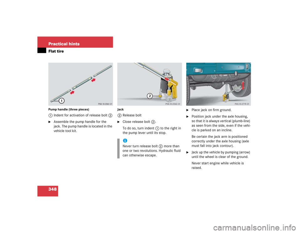
348 Practical hintsFlat tirePump handle (three pieces)1Indent for activation of release bolt2�
Assemble the pump handle for the
jack. The pump handle is located in the
vehicle tool kit.
Jack2Release bolt�
Close release bolt2.
To do so, turn indent1 to the right in
the pump lever until its stop.
�
Place jack on firm ground.
�
Position jack under the axle housing,
so that it is always vertical (plumb-line)
as seen from the side, even if the vehi-
cle is parked on an incline.
Be certain the jack arm is positioned
correctly under the axle housing (axle
must fall into jack contour).
�
Jack up the vehicle by pumping (arrow)
until the wheel is clear of the ground.
Never start engine while vehicle is
raised.
iNever turn release bolt2 more than
one or two revolutions. Hydraulic fluid
can otherwise escape.
Page 349 of 416

349 Practical hints
Flat tire
Removing the wheel�
Remove the wheel bolts.
�
Remove the wheel.Mounting the new wheel
�
Clean contact surfaces of wheel and
wheel hub.
�
Push the wheel onto the wheel hub and
press firmly.
�
Insert wheel bolts and tighten them
slightly.
!Do not place wheel bolts in sand or dirt.
This could result in damage to the bolt
and wheel hub threads.Warning!
G
Make sure no one is injured when removing
the wheel.
Grip wheel from the sides.
Keep hands from beneath the wheel.
Warning!
G
Always replace wheel bolts that are dam-
aged or rusted.
Never apply oil or grease to wheel bolts.
Damaged wheel hub threads should be re-
paired immediately. Do not continue to drive
under these circumstances! Contact an au-
thorized Mercedes-Benz Light Truck Center
or call Roadside Assistance.
Incorrect wheel bolts or improperly tight-
ened wheel bolts can cause the wheel to
come off. This could cause an accident.
Make sure to use the correct wheel bolts.
Warning!
G
Use only genuine equipment
Mercedes-Benz wheel bolts. Other wheel
bolts may come loose.
Do not tighten the wheel bolts when the ve-
hicle is raised. Otherwise the vehicle could
tip over.
Page 350 of 416
.
The vehicle is resting fully on its own
weight.
�
R")
350 Practical hintsFlat tireLowering the vehicle�
Using the pump lever, open the lower-
ing screw on the jack approximately
one turn (
�page 348).
The vehicle is resting fully on its own
weight.
�
Remove the jack.
After use, disassemble pump handle
(�page 348) and store jack in the des-
ignated storage compartment
(�page 322).
1-5 Wheel bolts
�
Tighten the five wheel bolts evenly, fol-
lowing the diagonal sequence illustrat-
ed (1 to 5), until all bolts are tight.
Observe a tightening torque of 97 lb-ft
(130 Nm).
�
Press the jack piston in again and close
the lowering screw. Store the jack
(�page 322) and the other vehicle
tools (
�page 321).
�
After changing the wheel, secure the
damaged wheel on the spare wheel
mounting bracket (
�page 324). Make
sure the wheel cannot come loose.
�
Check the tire inflation pressure and
correct it if necessary.
A table with the tire pressure values for
your vehicle is located on the fuel filler
flap.
Warning!
G
Have the tightening torque checked after
changing a wheel as soon as possible. The
wheels could come loose if they are not
tightened to a torque of 97 lb-ft (130 Nm).
Page 369 of 416

369 Technical data
Rims and tires
�Rims and tires
Use only tires and rims which have been
specifically developed for your vehicle and
tested and approved by Mercedes-Benz.
Other tires and rims can have detrimental
effects, such as:�
Poor handling characteristics
�
Increased noise
�
Increased fuel consumption
!Moreover, tires and rims not approved
by Mercedes-Benz may, under load,
exhibit dimensional variations and dif-
ferent tire deformation characteristics
that could cause them to come into
contact with the vehicle body or axle
parts. Damage to the tires or the vehi-
cle may be the result.
iFurther information on tires and rims is
available at any authorized
Mercedes-Benz Light Truck Center.
A placard with the recommended tire
inflation pressures is located on the
driver’s door B-pillar. Some vehicles
may have supplemental tire inflation
pressure information for driving at high
speeds (
�page 258) or for vehicle
loads less than the maximum loaded
vehicle condition. If such information is
provided, it can be found on the placard
located on the inside of the fuel filler
flap. The tire inflation pressure should
be checked regularly and should only
be adjusted on cold tires. Follow tire
manufacturer’s maintenance recom-
mendation included with vehicle.
Page 381 of 416

Prevents the wheels from locking up
during braking so that the vehicle can
continue to be steered.
Accessory weight
(
�page 271)
Air pressure
(�pag")
381 Technical terms
ABS
(A
ntilock B
rake S
ystem)
Prevents the wheels from locking up
during braking so that the vehicle can
continue to be steered.
Accessory weight
(
�page 271)
Air pressure
(�page 271)
Aspect ratio
(�page 271)
BabySmart
TM1
airbag deactivation
system
This system detects if a special system
compatible child restraint seat is in-
stalled on the front passenger seat. The
system will automatically deactivate
the passenger front airbag when such a
seat is properly installed (indicator
lamp7 in the center console
comes on).BabySmart
TM
compatible child seats
Special restraint system for children.
The sensor system for the passenger
seat prevents deployment of the pas-
senger front airbag if a BabySmart
TM
compatible child seat is installed. See
an authorized Mercedes-Benz Light
Truck Center for availability.
BAS
(B
rake A
ssist S
ystem)
System for potentially reducing braking
distances in emergency braking situa-
tions. The system is activated when it
senses an emergency based on how
fast the brake is applied.
Bar
(
�page 271)
Bead
(�page 271)CAC
(C
ustomer A
ssistance C
enter)
Mercedes-Benz customer service cen-
ter, which can help you with any ques-
tions about your vehicle and provide
assistance in the event of a break-
down.
CAN system
(C
ontroller A
rea N
etwork)
Data bus network serving to control ve-
hicle functions such as door locking or
windshield wiping.
Cockpit
All instruments, switches, buttons and
indicator/warning lamps in the passen-
ger compartment needed for vehicle
operation and monitoring.
Cold tire inflation pressure
(
�page 271)
1BabySmart
TM is a trademark of Siemens
Automotive Corp.
Page 383 of 416

(
�page 271)
Gear range
Number of gears which are available to
the automatic transmission for shifting.
The automatic gear shifting process
c")
383 Technical terms
GAWR
(G
ross A
xle W
eight R
ating)
(
�page 271)
Gear range
Number of gears which are available to
the automatic transmission for shifting.
The automatic gear shifting process
can be adapted to specific operating
conditions using the gear selector le-
ver.
GPS
(Global P
ositioning S
ystem)
Satellite-based system for relaying
geographic location information to and
from vehicles equipped with special re-
ceivers. Employs CD digital maps for
navigation.
GVW
(G
ross V
ehicle W
eight)
(
�page 272)
GTW
(Gross T
railer W
eight)
(
�page 271)GVWR
(G
ross V
ehicle W
eight R
ating)
(
�page 272)
Instrument cluster
The displays and indicator/warning
lamps in the driver’s field of vision, in-
cluding the tachometer, speedometer,
engine temperature and fuel gauge.
Kickdown
Depressing the accelerator past the
point of resistance shifts the transmis-
sion down to the lowest possible gear.
This very quickly accelerates the vehi-
cle and should not be used for normal
acceleration needs.
Kilopascal (kPa)
(�page 272)
Line of fall
The direct line that an object moves
downhill when influenced by the force
of gravity alone. Lock button
Button on the door which indicates
whether the door is locked or un-
locked. Pushing the lock button down
on an individual door from inside will
lock that door.
Maintenance System (U.S. vehicles)
Maintenance service indicator in the
speedometer display that informs the
driver when the next vehicle mainte-
nance service is due. The Maintenance
System tracks distance driven and the
time elapsed since your last mainte-
nance service, and calls for the next
maintenance service accordingly.
Maximum load rating
(
�page 272)
Maximum loaded vehicle weight
(�page 272)
Maximum tire inflation pressure
(�page 272)