Page 25 of 416
25 At a glance
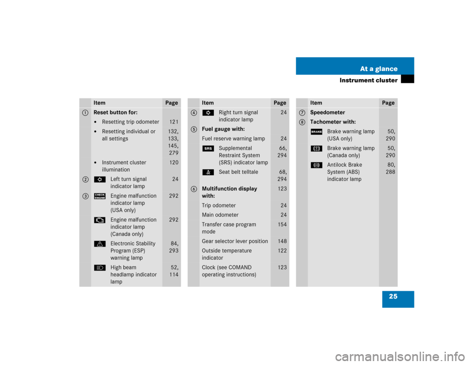
Instrument cluster
Item
Page
1
Reset button for:�
Resetting trip odometer
121
�
Resetting individual or
all settings
132,
133,
145,
279
�
Instrument cluster
illumination
120
2
LLeft turn signal
indicator lamp
24
3
?Engine malfunction
indicator lamp
(USA only)
292
±Engine malfunction
indicator lamp
(Canada only)
292
vElectronic Stability
Program (ESP)
warning lamp
84,
293
AHigh beam
headlamp indicator
lamp
52,
114
Item
Page
4
KRight turn signal
indicator lamp
24
5
Fuel gauge with:Fuel reserve warning lamp
24
1Supplemental
Restraint System
(SRS) indicator lamp
66,
294
68,
294
6
Multifunction display
with:
123
Trip odometer
24
Main odometer
24
Transfer case program
mode
154
Gear selector lever position
148
Outside temperature
indicator
122
Clock (see COMAND
operating instructions)
123
Item
Page
7
Speedometer
8
Tachometer with:;Brake warning lamp
(USA only)
50,
290
3Brake warning lamp
(Canada only)
50,
290
-Antilock Brake
System (ABS)
indicator lamp
80,
288
Page 120 of 416
.
1Reset button
The instrument clus")
120 Controls in detailInstrument clusterA full view illustration of the instrument
cluster can be found in the “At a glance”
section of this manual (
�page 24).
1Reset button
The instrument cluster is activated when
you:
�
Open a door.
�
Switch on ignition.
�
Press reset button1.
�
Switch on the exterior lamps.
You can change the instrument cluster set-
tings in the Instrument cluster submenu of
the control system (
�page 135).
Instrument cluster illumination
Use the reset button to adjust the illumina-
tion brightness for the instrument cluster.
To brighten illumination�
Turn reset button1 in the instrument
cluster clockwise.
The instrument cluster illumination will
brighten.To dim illumination
�
Turn reset button1 in the instrument
cluster counterclockwise.
The instrument cluster illumination will
dim.
Coolant temperature display
iThe instrument cluster illumination is
dimmed or brightened automatically to
suit ambient light conditions.
The instrument cluster illumination will
also be adjusted automatically when
you switch on the vehicle’s exterior
lamps.
Warning!
G
�
Driving when your engine is badly over-
heated can cause some fluids which
may have leaked into the engine com-
partment to catch fire. You could be se-
riously burned.
�
Steam from an overheated engine can
cause serious burns and can occur just
by opening the hood. Stay away from
the engine if you see or hear steam com-
ing from it.
Turn off the engine, get out of the vehicle
and do not stand near the vehicle until the
engine has cooled down.
Page 123 of 416

123 Controls in detail
Control system
�Control system
The control system is activated as soon as
the SmartKey in the starter switch is
turned to position1. The control system
enables you to�
call up information about your vehicle
�
change vehicle settings
For example, you can use the control sys-
tem to find out when your vehicle is next
due for service, to set the language for
messages in the instrument cluster display
and much more.
The control system relays information to
the multifunction display.
Multifunction display
1Trip odometer
2Main odometer
3Outside temperature
4Clock
1
5Current gear selector lever position
6Transfer case program mode
Warning!
G
A driver’s attention to the road and traffic
conditions must always be his /her primary
focus when driving.
For your safety and the safety of others, se-
lecting features through the multifunction
steering wheel should only be done by the
driver when traffic and road conditions per-
mit it to be done safely.
Bear in mind that at a speed of just 30 mph
(approximately 50 km/h), your vehicle is
covering a distance of 44 feet
(approximately 14 m) every second.
1See separate operating instructions for the
COMAND system for clock setting.
Page 325 of 416

325 Practical hints
Unlocking/locking in an emergency
�Unlocking/locking in an emergency
Unlocking the vehicle
If you are unable to unlock the vehicle with
the SmartKey, open the driver’s door and
the tailgate using the mechanical key.
The passenger door cannot be unlocked
manually.
1Mechanical key locking tab
2Mechanical key
�
Move locking tab1 in direction of ar-
row and slide the mechanical key2
out of the housing.
Unlocking the driver’s door
�
Unlock the door with the mechanical
key. To do so, push the mechanical key
in the lock until it stops and turn it to
the left.Unlocking the tailgate
If you are unable to unlock the tailgate with
the SmartKey, open the tailgate with the
mechanical key as follows:
1Unlocking in an emergency
2Lock cylinder
3Handle
�
Insert the mechanical key into lock
cylinder2.
�
Turn the mechanical key counterclock-
wise to position1 and release it.
�
Remove the mechanical key.
iUnlocking your vehicle with the me-
chanical key will trigger the anti-theft
alarm system. To cancel the alarm, do
one of the following:�
Press button Œ or ‹ on the
SmartKey.
�
Insert the SmartKey in the starter
switch.
��
Page 328 of 416
328 Practical hintsOpening/closing in an emergencyTilt/sliding sunroof
You can open or close the tilt/sliding sun-
roof manually in the case of power failure.
The tilt/sliding sunroof drive is located on
the left side (driver’s side) of the cargo
compartment behind the rear panel trim.
1Edge protection
2Rear panel trim�
Take the vehicle tool kit out from its
storage compartment (
�page 321).
�
Open the tailgate.
�
Remove edge protection1 from door
pillar.
�
Remove rear panel trim2.
3Key (vehicle tool kit)
4Screwdriver (vehicle tool kit)
�
Fit key3 into hexagon nut of drive.
�
Insert screwdriver4 into the key as a
lever.
�
Turn screwdriver4 clockwise to:�
slide sunroof closed
�
raise sunroof at the rear
�
Turn screwdriver4 counterclockwise
to:�
slide sunroof open
�
lower sunroof at the rear
iDo not disconnect electrical connec-
tors.
Page 338 of 416
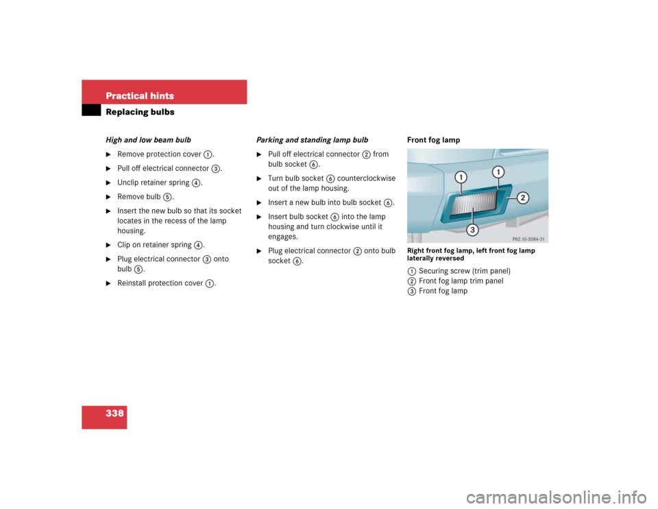
338 Practical hintsReplacing bulbsHigh and low beam bulb�
Remove protection cover1.
�
Pull off electrical connector3.
�
Unclip retainer spring4.
�
Remove bulb5.
�
Insert the new bulb so that its socket
locates in the recess of the lamp
housing.
�
Clip on retainer spring4.
�
Plug electrical connector3 onto
bulb5.
�
Reinstall protection cover1.Parking and standing lamp bulb
�
Pull off electrical connector2 from
bulb socket6.
�
Turn bulb socket6 counterclockwise
out of the lamp housing.
�
Insert a new bulb into bulb socket6.
�
Insert bulb socket6 into the lamp
housing and turn clockwise until it
engages.
�
Plug electrical connector2 onto bulb
socket6.Front fog lamp
Right front fog lamp, left front fog lamp
laterally reversed1Securing screw (trim panel)
2Front fog lamp trim panel
3Front fog lamp
Page 340 of 416
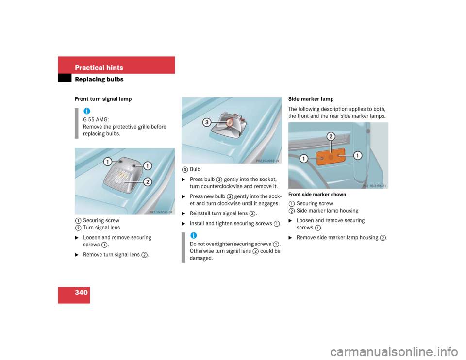
340 Practical hintsReplacing bulbsFront turn signal lamp
1Securing screw
2Turn signal lens�
Loosen and remove securing
screws1.
�
Remove turn signal lens2.3Bulb
�
Press bulb3 gently into the socket,
turn counterclockwise and remove it.
�
Press new bulb3 gently into the sock-
et and turn clockwise until it engages.
�
Reinstall turn signal lens2.
�
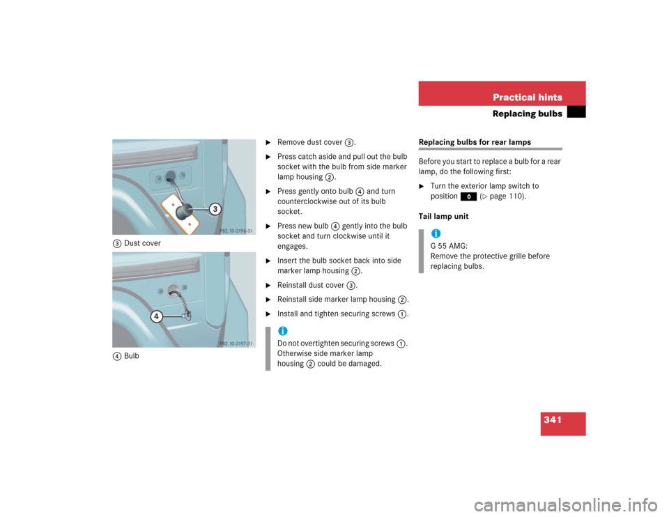
Install and tighten securing screws1.Side marker lamp
The following description applies to both,
the front and the rear side marker lamps.
Front side marker shown1Securing screw
2Side marker lamp housing�
Loosen and remove securing
screws1.
�
Remove side marker lamp housing2.
iG55AMG:
Remove the protective grille before
replacing bulbs.
iDo not overtighten securing screws1.
Otherwise turn signal lens2 could be
damaged.
Page 341 of 416
341 Practical hints
Replacing bulbs
3Dust cover
4Bulb
�
Remove dust cover3.
�
Press catch aside and pull out the bulb
socket with the bulb from side marker
lamp housing2.
�
Press gently onto bulb4 and turn
counterclockwise out of its bulb
socket.
�
Press new bulb4 gently into the bulb
socket and turn clockwise until it
engages.
�
Insert the bulb socket back into side
marker lamp housing2.
�
Reinstall dust cover3.
�
Reinstall side marker lamp housing2.
�
Install and tighten securing screws1.
Replacing bulbs for rear lamps
Before you start to replace a bulb for a rear
lamp, do the following first:�
Turn the exterior lamp switch to
positionM (
�page 110).
Tail lamp unit
iDo not overtighten securing screws1.
Otherwise side marker lamp
housing2 could be damaged.
iG55AMG:
Remove the protective grille before
replacing bulbs.