Page 358 of 416

358 Practical hintsTowing the vehicleTransporting the vehicle
When transporting the vehicle, you can use
the towing eyes for pulling the vehicle onto
a trailer or transporter. �
Move the gear selector lever to posi-
tion N.
�
Shift the transfer case to neutral posi-
tion N.
�
To avoid damaging the vehicle, it
should only be tied down on the
wheels / wheel rims, not on chassis
components such as the transverse
link or trailing arm.Towing the vehicle - various problem
scenarios�
Comply with all towing information
(�page 356).
In case of engine damage, transmission
damage or malfunctions in electrical
equipment
�
Move the gear selector lever to posi-
tion N.
�
Shift the transfer case to neutral posi-
tion N.In case of transfer case damage or for
towing vehicle distances exceeding
30 miles (50 km)
The propeller shafts to the drive axles must
be removed.
In case of front axle damage
Raise the front axle when towing. The pro-
peller shaft between the rear axle and the
transfer case must be removed.
In case of rear axle damage
When the rear axle is raised, the vehicle
can only be towed with a wheel lift or a dol-
ly placed under its front wheels.!When removing drive shaft, place M10
nuts on bolts as distance sleeves and
tighten using M8 nuts.
Always install new self-locking nuts
when reinstalling the drive shaft.
Page 359 of 416
359 Practical hints
Towing the vehicle
Front towing eye
In the front, the towing eye is located on
the driver’s side under the bumper.
1Towing eye
Rear towing eye
In the rear, the towing eye is located on the
driver’s side under the bumper.
1Towing eye
Freeing a stranded vehicle
Freeing a stranded vehicle, on which the
wheels are dug into sand or mud, should
be done with the greatest of care, especial-
ly if the vehicle is heavily loaded.
Avoid pulling the vehicle jerkily or diago-
nally, since it could result in damage to the
chassis alignment.
Never try to free a vehicle that is still cou-
pled to a trailer.
If possible, a vehicle equipped with trailer
hitch receiver should be pulled backward
in its own previously made tracks.
Page 370 of 416
370 Technical dataRims and tires Rims and Tires
G 500
G55AMG
Rims (light alloy)
71/2 J x18 H2
91/2 J x 18 EH2
Wheel offset
1.69 in (43 mm)
1.97 in (50 mm)
All season tires (radial-ply tires)
265/60 R18 110V M+S
285/55 R18 113V M+S
1
1Must not be used with snow chains.
Page 371 of 416
371 Technical data
Rims and tires
Spare wheels
G 500
G55AMG
Rims (light alloy)
71/2 J x18 H2
71/2 J x18 H2
Wheel offset
1.69 in (43 mm)
1.69 in (43 mm)
All season tires (radial-ply tires)
265/60 R18 110V M+S
265/60 R18 110V M+S
Page 373 of 416

373 Technical data
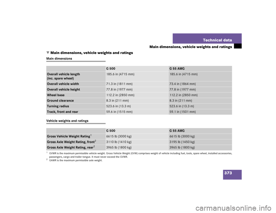
Main dimensions, vehicle weights and ratings
�Main dimensions, vehicle weights and ratings
Main dimensionsVehicle weights and ratings
G 500
G55AMG
Overall vehicle length
(inc. spare wheel)
185.6 in (4715 mm)
185.6 in (4715 mm)
Overall vehicle width
71.3 in (1811 mm)
73.4 in (1864 mm)
Overall vehicle height
77.8 in (1977 mm)
77.8 in (1977 mm)
Wheel base
112.2 in (2850 mm)
112.2 in (2850 mm)
Ground clearance
8.3 in (211 mm)
8.3 in (211 mm)
Turning radius
523.6 in (13.3 m)
523.6 in (13.3 m)
Track, front and rear
59.6 in (1515 mm)
59.1 in (1501 mm)
G 500
G55AMG
Gross Vehicle Weight Rating
1
1GVWR is the maximum permissible vehicle weight. Gross Vehicle Weight (GVW) comprises weight of vehicle including fuel, tools, spare wheel, installed accessories,
passengers, cargo and trailer tongue. It must never exceed the GVWR.
6615 lb (3000 kg)
6615 lb (3000 kg)
Gross Axle Weight Rating, front
2
2GAWR is the maximum permissible axle weight.
3110 lb (1410 kg)
3195 lb (1450 kg)
Gross Axle Weight Rating, rear
2
3965 lb (1800 kg)
3965 lb (1800 kg)
Page 374 of 416

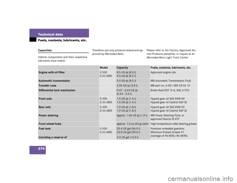
374 Technical dataFuels, coolants, lubricants, etc.Capacities
Vehicle components and their respective
lubricants must match.Therefore use only products tested and ap-
proved by Mercedes-Benz.Please refer to the Factory Approved Ser-
vice Products pamphlet, or inquire at an
Mercedes-Benz Light Truck Center.
Model
Capacity
Fuels, coolants, lubricants, etc.
Engine with oil filter
G 500
G55AMG
8.5 US qt (8.0 l)
9.0 US qt (8.5 l)
Approved engine oils
Automatic transmission
9.0 US qt (8.5 l)
MB Automatic Transmission Fluid
Transfer case
2.96 US qt (2.8 l)
MB part no. A 001 989 28 03 10
Differential lock mechanism
0.47 - 0.63 US qt
(0.45 - 0.6 l)
Brake fluid DOT 3+4, SAE J1703
Front axle
G 500
G55AMG
1.5 US qt (1.4 l)
1.5 US qt (1.4 l)
Hypoid gear oil SAE 85W-90
Hypoid gear oil Castrol SAF-XJ
Rear axle
G 500
G55AMG
1.9 US qt (1.8 l)
1.9 US qt (1.8 l)
Hypoid gear oil SAE 85W-90
Hypoid gear oil Castrol SAF-XJ
Power steering
approx. 1.06 US qt (1.0 l)
MB Power Steering Fluid, or
approved Dexron III ATF
Front wheel hubs
approx. 1.5 oz (43 g) each
High temperature roller bearing grease
Fuel tank
including a reserve of
G 500
G55AMG
25.4 US gal (96.0 l)
23.8 US gal (90.0 l)
3.4 US gal (13.0 l)
Premium unleaded gasoline:
Minimum Posted Octane 91
(average of 96 RON / 86 MON)
Page 381 of 416

381 Technical terms
ABS
(A
ntilock B
rake S
ystem)
Prevents the wheels from locking up
during braking so that the vehicle can
continue to be steered.
Accessory weight
(
�page 271)
Air pressure
(�page 271)
Aspect ratio
(�page 271)
BabySmart
TM1
airbag deactivation
system
This system detects if a special system
compatible child restraint seat is in-
stalled on the front passenger seat. The
system will automatically deactivate
the passenger front airbag when such a
seat is properly installed (indicator
lamp7 in the center console
comes on).BabySmart
TM
compatible child seats
Special restraint system for children.
The sensor system for the passenger
seat prevents deployment of the pas-
senger front airbag if a BabySmart
TM
compatible child seat is installed. See
an authorized Mercedes-Benz Light
Truck Center for availability.
BAS
(B
rake A
ssist S
ystem)
System for potentially reducing braking
distances in emergency braking situa-
tions. The system is activated when it
senses an emergency based on how
fast the brake is applied.
Bar
(
�page 271)
Bead
(�page 271)CAC
(C
ustomer A
ssistance C
enter)
Mercedes-Benz customer service cen-
ter, which can help you with any ques-
tions about your vehicle and provide
assistance in the event of a break-
down.
CAN system
(C
ontroller A
rea N
etwork)
Data bus network serving to control ve-
hicle functions such as door locking or
windshield wiping.
Cockpit
All instruments, switches, buttons and
indicator/warning lamps in the passen-
ger compartment needed for vehicle
operation and monitoring.
Cold tire inflation pressure
(
�page 271)
1BabySmart
TM is a trademark of Siemens
Automotive Corp.
Page 382 of 416

382 Technical termsCOMAND
(C
ockpit M
anagement and D
ata
System)
Information and operating center for
vehicle sound and communications
systems, including the radio and the
navigation system, as well as other op-
tional equipment (CD changer, tele-
phone, etc.).
Control system
The control system is used to call up
vehicle information and to change
component settings. Information and
messages appear in the multifunction
display. The driver uses the buttons on
the multifunction steering wheel to
navigate through the system and to ad-
just settings.
Differential locks
On slippery surfaces, differential locks
prevent one wheel of an axle from spin-
ning while the other wheel stands still,
resulting in driving force no longer be-
ing transferred.Cruise control
Driving convenience system that auto-
matically maintains the vehicle speed
set by the driver.
Curb weight
(
�page 271)
DOT
(Department o
f Transportation)
(
�page 271)
Engine number
The number set by the manufacturer
and placed on the cylinder block to
uniquely identify each engine pro-
duced.
Engine oil viscosity
Measurement for the inner friction (vis-
cosity) of the oil at different tempera-
tures. The higher the temperature an
oil can tolerate without becoming thin,
or the lower the temperature it can tol-
erate without becoming viscous, the
better the viscosity.ESP
(E
lectronic S
tability Pr
ogram)
Improves vehicle handling and direc-
tional stability.
ETD
(E
mergency T
ensioning D
evice)
Device which deploys in certain frontal
and rear collisions exceeding the sys-
tem's threshold to tighten the seat
belts.
->SRS
FSS (Canada vehicles)
(F
lexible S
ervice S
ystem)
Maintenance service indicator in the
speedometer display that informs the
driver when the next vehicle mainte-
nance service is due. FSS evaluates en-
gine temperature, oil level, vehicle
speed, engine speed, distance driven
and the time elapsed since your last
service, and calls for the next mainte-
nance service accordingly.