Page 419 of 498
.
1Flap
2On/off switch
3Electrical plug
4Air hose with pressure gauge and vent
screw
5Union nut
�
Open flap 1")
417 Practical hints
Flat tire
�
Take the electric air pump out of the
trunk (
�page 391).
1Flap
2On/off switch
3Electrical plug
4Air hose with pressure gauge and vent
screw
5Union nut
�
Open flap 1 on electric air pump.
�
Pull out electrical plug 3 and air hose
with pressure gauge 4.
�
Remove the valve cap from the
collapsible tire valve.
�
Screw air hose 4 onto the collapsible
tire valve.
�
Insert electrical plug 3 into vehicle
cigarette lighter socket.
�
Turn the SmartKey in the starter switch
to position1.
�
Press I on electric air pump switch 2.
The electric air pump should now
switch on and inflate the collapsible
tire.
�
Inflate the tire to approximately 36 psi
(2.5 bar).
This takes about five minutes for the
collapsible tire. Air hose 4 and union
nut5 can become hot duration infla-
tion. Exercise proper caution to avoid
burning yourself when using the equip-
ment.
�
Press 0 on electric air pump switch 2.
�
Turn the SmartKey in the starter switch
to position0.
�
If the tire pressure is above 36 psi
(2.5 bar), release excess tire pressure
using the vent screw.!Do not operate the electric air pump
longer than six minutes without inter-
ruption. Otherwise it may overheat.
You may operate the electric air pump
again after it has cooled off.
��
Page 420 of 498

418 Practical hintsFlat tire�
Detach the electric air pump.
�
Store the electrical plug and the air
hose behind the flap and place the
electric air pump back in the trunk.Lowering the vehicle
�
Lower vehicle by turning crank
counterclockwise until vehicle is
resting fully on its own weight.
�
Remove the jack.1 - 5Wheel bolts
�
Tighten the five wheel bolts evenly,
following the diagonal sequence
illustrated (1to5), until all bolts are
tight. Observe a tightening torque
of 80 lb-ft (110 Nm).
Warning!
G
Follow recommend inflation pressures.
Do not overinflate tires. Overinflating tires
can result in sudden deflation (blowout) be-
cause they are more likely to become punc-
tured or damaged by road debris, potholes,
etc.
Do not underinflate tires. Underinflated tires
wear unevenly, adversely affect handling
and fuel economy, and are more likely to fail
from being overheated.
Warning!
G
Vehicles with collapsible tire
(CLK 55 AMG only):
Inflate collapsible tire only after the wheel is
properly mounted.
Inflate the collapsible tire using the electric
pump (
�page 416) before
lowering the ve-
hicle.
��
Page 421 of 498
419 Practical hints
Flat tire
Before storing the jack, it should be fully
collapsed, with handle folded in (storage
position) (
�page 391).
�
Store the jack and the other vehicle
tools in the trunk.Warning!
G
Have the tightening torque checked after
changing a wheel. The wheels could come
loose if they are not tightened to a torque
of 80 lb-ft (110 Nm).
Page 429 of 498
427 Practical hints
Towing the vehicle
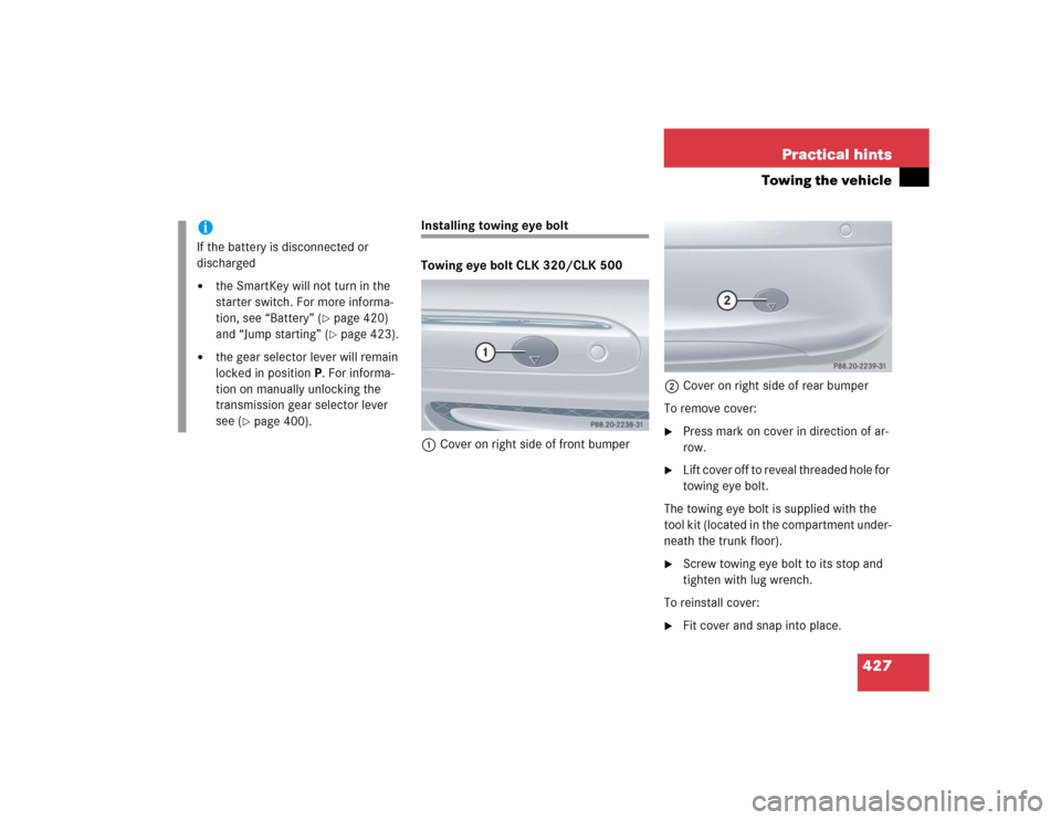
Installing towing eye bolt
Towing eye bolt CLK 320/CLK 500
1Cover on right side of front bumper2Cover on right side of rear bumper
To remove cover:
�
Press mark on cover in direction of ar-
row.
�
L i f t c o v e r o f f t o r e v e a l t h r e a d e d h o l e f o r
towing eye bolt.
The towing eye bolt is supplied with the
tool kit (located in the compartment under-
neath the trunk floor).
�
Screw towing eye bolt to its stop and
tighten with lug wrench.
To reinstall cover:
�
Fit cover and snap into place.
iIf the battery is disconnected or
discharged�
the SmartKey will not turn in the
starter switch. For more informa-
tion, see “Battery” (
�page 420)
and “Jump starting” (�page 423).
�
the gear selector lever will remain
locked in positionP. For informa-
tion on manually unlocking the
transmission gear selector lever
see (
�page 400).
Page 430 of 498

428 Practical hintsTowing the vehicleTowing eye bolt CLK 55 AMG
Towing eye bolt in front bumper
The cover for the towing eye bolt in the
front bumper is identical to the cover on
the models CLK320/CLK500.
To remove and to reinstall cover, see “Tow-
ing eye bolt CLK 320/CLK 500”
(�page 427)
Towing eye bolt in rear bumper
1Cover on right side of rear bumper
2Recess in the coverTo remove cover:
�
Insert flat, blunt object as a lever in re-
cess 2 on the edge of cover 1.
�
Loosen cover 1 from the bumper us-
ing lever, to reveal threaded hole for
towing eye bolt.
The towing eye bolt is supplied with the
tool kit (located in the compartment
underneath the trunk floor).
�
Screw towing eye bolt to its stop and
tighten with lug wrench.To reinstall cover:
�
Hook right-hand side of the cover into
opening.
�
Slide cover as far as it will go in the di-
rection of the arrow3.
�
Gently press left-hand side of cover in
direction of the arrow4.
The hooks on the left-hand side en-
gage.iWhen closing the cover, make sure the
cover’s check strap does not get
caught.
Page 431 of 498
429 Practical hintsFuses
�Fuses
The electrical fuses in your vehicle serve to
stop the supply of electricity to a device
that is malfunctioning. This helps to
prevent damage to the other vehicle
electronics.
The following aids are available to help you
change fuses (
�page 430):
�
Fuse chart
�
Spare fuses
�
Fuse extractorThe electrical fuses are located in different
fuse boxes:
�
Main fuse box in passenger
compartment (
�page 430)
�
Fuse box in engine compartment
(�page 431)
�
Fuse box in trunk (
�page 432)
Warning!
G
Only use fuses approved for Mercedes-Benz
with the specified amperage for the system
in question. Otherwise, a short circuit could
result and cause a fire.!Only install fuses that have been tested
and approved by Mercedes-Benz and
that have the specified amperage
rating.
Otherwise, electrical parts or systems
could be damaged.
Never attempt to repair or bridge a
blown fuse. Have the cause determined
and remedied by an authorized
Mercedes-Benz Center.
Page 432 of 498
430 Practical hintsFusesAids for changing fuses
Fuse chart
The fuse chart is found in the main fuse
box in the passenger compartment
(�page 430). The amperages of the fuses
are also given there.
Spare fuses
Spare fuses are found in the vehicle tool kit
in the spare wheel well (
�page 390).
Fuse extractor
The fuse extractor is located in the cover of
the auxiliary fuse box in the trunk
(
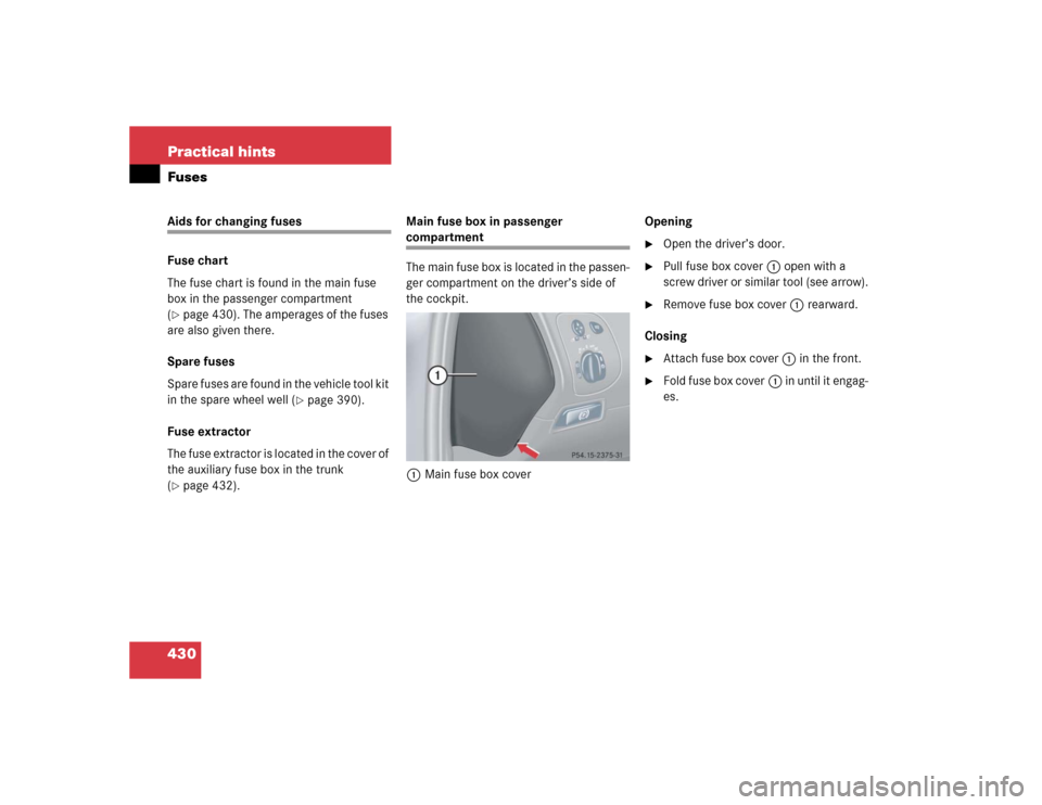
�page 432).Main fuse box in passenger
compartment
The main fuse box is located in the passen-
ger compartment on the driver’s side of
the cockpit.
1Main fuse box coverOpening
�
Open the driver’s door.
�
Pull fuse box cover1 open with a
screw driver or similar tool (see arrow).
�
Remove fuse box cover1 rearward.
Closing
�
Attach fuse box cover1 in the front.
�
Fold fuse box cover1 in until it engag-
es.
Page 434 of 498
432 Practical hintsFusesClosing fuse box�
Make sure that the sealing rubber is
properly positioned.
�
Press fuse box cover4 down and
secure with clamps5.
Installing cover
�
Insert cover1 sideways into
retainer3.
�
Twist screws2 90° clockwise.
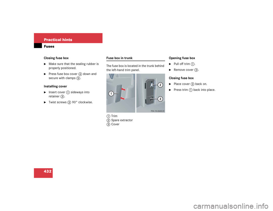
Fuse box in trunk
The fuse box is located in the trunk behind
the left-hand trim panel.
1Trim
2Spare extractor
3CoverOpening fuse box
�
Pull off trim1.
�
Remove cover3.
Closing fuse box
�
Place cover3 back on.
�
Press trim1 back into place.