Page 389 of 474
388 Practical hintsReplacing bulbsFront turn signal lamp bulb�
Turn bulb socket3 counterclockwise
and remove it.
�
Press gently onto the bulb and turn
counterclockwise out of bulb
socket3.
�
Press the new bulb gently into bulb
socket3 and turn clockwise until it
engages.
�
Place bulb socket3 back into the
lamp and turn it clockwise.Parking and standing lamp bulb
�
Turn housing cover2 counterclock-
wise and remove it.
�
Pull out bulb socket6 with the bulb.
�
Pull the bulb out of bulb socket6.
�
Press the new bulb into bulb socket6.
�
Press bulb socket6 back into the
lamp.
�
Align housing cover2 and turn it
clockwise.Bi-Xenon* headlamps
Warning!
G
Do not remove the cover
1
for the
Bi-Xenon headlamp. Because of high voltage
in Bi-Xenon lamps, it is dangerous to replace
the bulb or repair the lamp and its compo-
nents. We recommend that you have such
work done by a qualified technician.
Page 390 of 474

389 Practical hints
Replacing bulbs
Left headlamp, mirror-image of right
headlamp1Housing cover for Bi-Xenon headlamp
2Housing cover for high beam flasher,
parking and standing lamp3Bulb socket for turn signal lamp
4Bulb holder for high beam flasher
5Bulb socket for parking and standing
lamp bulb
High beam bulb for high beam flasher
�
Turn housing cover2 counterclock-
wise and remove it.
�
Turn bulb holder4 with the bulb coun-
terclockwise and remove it.
�
Pull the bulb at its socket out of bulb
holder4.
�
Insert the new bulb so that its socket
locates in the recess of bulb holder4
and is level to it.
�
Reinsert bulb holder4 w i t h t h e b u l b i n
the lamp and turn clockwise.
�
Align housing cover2 and turn it
clockwise.
Front turn signal lamp bulb
�
Turn bulb socket3 with the bulb
counterclockwise and remove it.
�
Press gently onto the bulb and turn
counterclockwise out of bulb
socket3.
�
Press the new bulb gently into bulb
socket3 and turn clockwise until it
engages.
�
Place bulb socket3 back into the
lamp and turn it clockwise.
Page 391 of 474

390 Practical hintsReplacing bulbsParking and standing lamp bulb�
Turn housing cover2 counterclock-
wise and remove it.
�
Pull out bulb socket5 with the bulb.
�
Pull the bulb out of bulb socket5.
�
Press the new bulb into bulb socket5.
�
Press bulb socket5 back into the
lamp.
�
Align housing cover2 and turn it
clockwise.Side marker lamp bulb
�
Carefully slide the lamp towards the
rear in direction of arrows.
�
Remove the front end first.
�
Turn the bulb socket with the bulb
counterclockwise and remove it.
�
Pull the bulb out of the bulb socket.
�
Insert the new bulb into the bulb sock-
et.
�
Place the bulb socket back into the
lamp and turn it clockwise.
�
To reinstall the lamp, set the rear end in
the bumper and let the front end en-
gage.
Replacing bulbs for rear lamps
Before you start to replace a bulb for a rear
lamp, do the following first:�
Turn the exterior lamp switch to
positionM (
�page 110).
Tail lamp unit
1Trim panel
2Latch
�
Open the trunk lid.
�
Turn latches1 on respective trim
panel2 clockwise.
�
Fold trim panel2 to the side.
Page 392 of 474

391 Practical hints
Replacing bulbs
3Tab
4Bulb socket for side marker lamp bulb�
Press tabs3 together.
�
Remove the bulb carrier.
�
Press gently onto the respective bulb
and turn counterclockwise out of its
bulb socket.
�
Press the new bulb gently into its bulb
socket and turn clockwise until it en-
gages.5Brake lamp bulb
6Backup lamp bulb
7Turn signal lamp bulb
8Rear fog lamp bulb (only driver’s side),
tail, parking and standing lamp
�
Reinstall the bulb carrier.
Let tabs3 engage.
�
Reinstall trim panel2.
�
Turn latches1 counterclockwise.Side marker lamp
The bulb socket for the side marker lamp
bulb is located between the bulb carrier
and the vehicle’s body.
�
Open the trunk lid.
�
Turn latches1 on respective trim
panel2 clockwise.
�
Fold trim panel2 to the side.
�
Pull bulb socket4 with the bulb out of
its holder.
�
Pull the bulb out of bulb socket4.
�
Press the new bulb into bulb socket4.
�
Press bulb socket4 back into its
holder.
�
Reinstall trim panel2.
�
Turn latches1 counterclockwise.
Page 401 of 474
400 Practical hintsFlat tireLowering the vehicle�
Lower vehicle by turning crank coun-
terclockwise until vehicle is resting ful-
ly on its own weight.
�
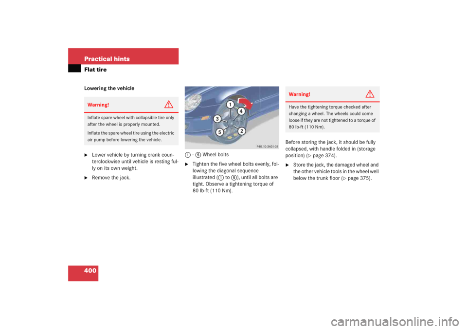
Remove the jack.1-5 Wheel bolts
�
Tighten the five wheel bolts evenly, fol-
lowing the diagonal sequence
illustrated (1 to 5), until all bolts are
tight. Observe a tightening torque of
80 lb-ft (110 Nm).Before storing the jack, it should be fully
collapsed, with handle folded in (storage
position) (
�page 374).
�
Store the jack, the damaged wheel and
the other vehicle tools in the wheel well
below the trunk floor (
�page 375).
Warning!
G
Inflate spare wheel with collapsible tire only
after the wheel is properly mounted.
Inflate the spare wheel tire using the electric
air pump before lowering the vehicle.
Warning!
G
Have the tightening torque checked after
changing a wheel. The wheels could come
loose if they are not tightened to a torque of
80 lb-ft (110 Nm).
Page 404 of 474
.
�")
403 Practical hints
Battery
Reconnecting the battery�
Turn off all electrical consumers.
�
Remove SmartKey from the starter
switch.
�
Connect the positive lead and fasten its
cover2 (
�page 402).
�
Connect the negative lead.
�
Reinstall the filter box (
�page 401).
Batteries contain materials that can harm
the environment if disposed of improperly.
Large 12-volt storage batteries contain
lead. Recycling of batteries is the preferred
method of disposal. Many states require
sellers of batteries to accept old batteries
for recycling.
Warning!
G
Never charge a battery while still installed in
the vehicle unless the accessory battery
charge unit approved by Mercedes-Benz is
being used. Gases may escape during charg-
ing and cause explosions that may result in
paint damage, corrosion or personal injury.
An accessory battery charge unit specially
adapted for Mercedes-Benz vehicles and
tested and approved by Mercedes-Benz is
available, permitting the charging of the bat-
tery in its installed position. Contact an au-
thorized Mercedes-Benz Center for
information and availability. Charge battery
in accordance with the instructions for the
accessory battery charger.
!NEVER invert the terminal connections!!The battery, its filler caps and the vent
tube must always be securely installed
when the vehicle is in operation.
iThe following procedures must be car-
ried out following any interruption of
battery power (e.g. due to reconnec-
tion):�
Set the clock (
�page 139) (vehi-
cles with COMAND*: see COMAND
operator’s manual).
�
Resynchronize side windows
(�page 240).
�
Resynchronize panorama roof with
power tilt/sliding panel*
(�page 246).
Page 412 of 474
411 Practical hintsFuses
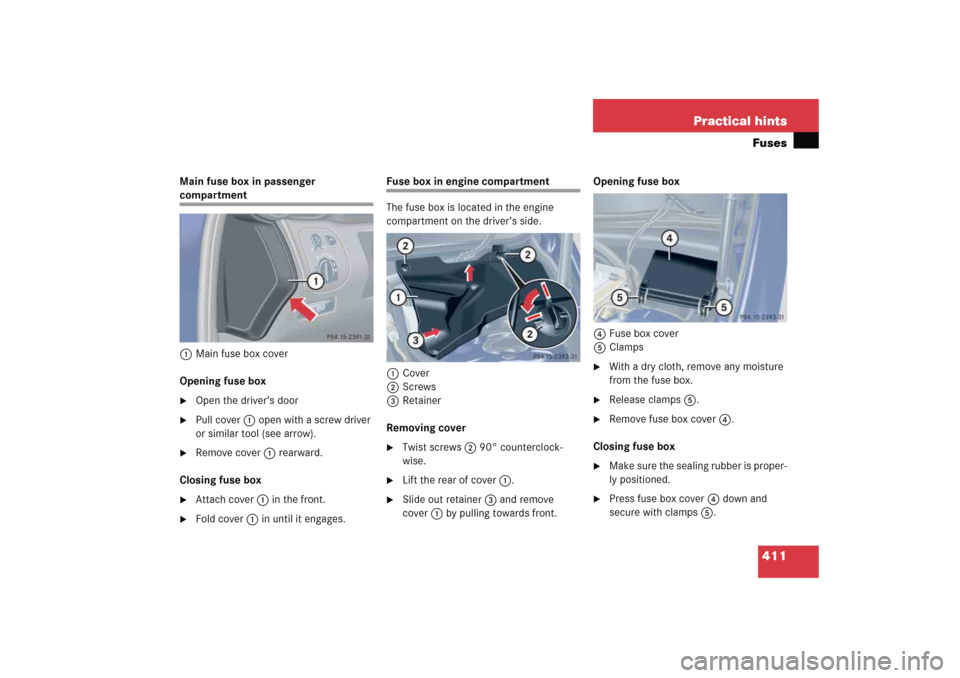
Main fuse box in passenger compartment
1Main fuse box cover
Opening fuse box�
Open the driver’s door
�
Pull cover1 open with a screw driver
or similar tool (see arrow).
�
Remove cover1 rearward.
Closing fuse box
�
Attach cover1 in the front.
�
Fold cover1 in until it engages.
Fuse box in engine compartment
The fuse box is located in the engine
compartment on the driver’s side.
1Cover
2Screws
3Retainer
Removing cover�
Twist screws2 90° counterclock-
wise.
�
Lift the rear of cover1.
�
Slide out retainer3 and remove
cover1 by pulling towards front.Opening fuse box
4Fuse box cover
5Clamps
�
With a dry cloth, remove any moisture
from the fuse box.
�
Release clamps5.
�
Remove fuse box cover4.
Closing fuse box
�
Make sure the sealing rubber is proper-
ly positioned.
�
Press fuse box cover4 down and
secure with clamps5.
Page 413 of 474
412 Practical hintsFusesInstalling cover�
Insert cover1 sideways into
retainer3.
�
Twist screws2 90° clockwise.
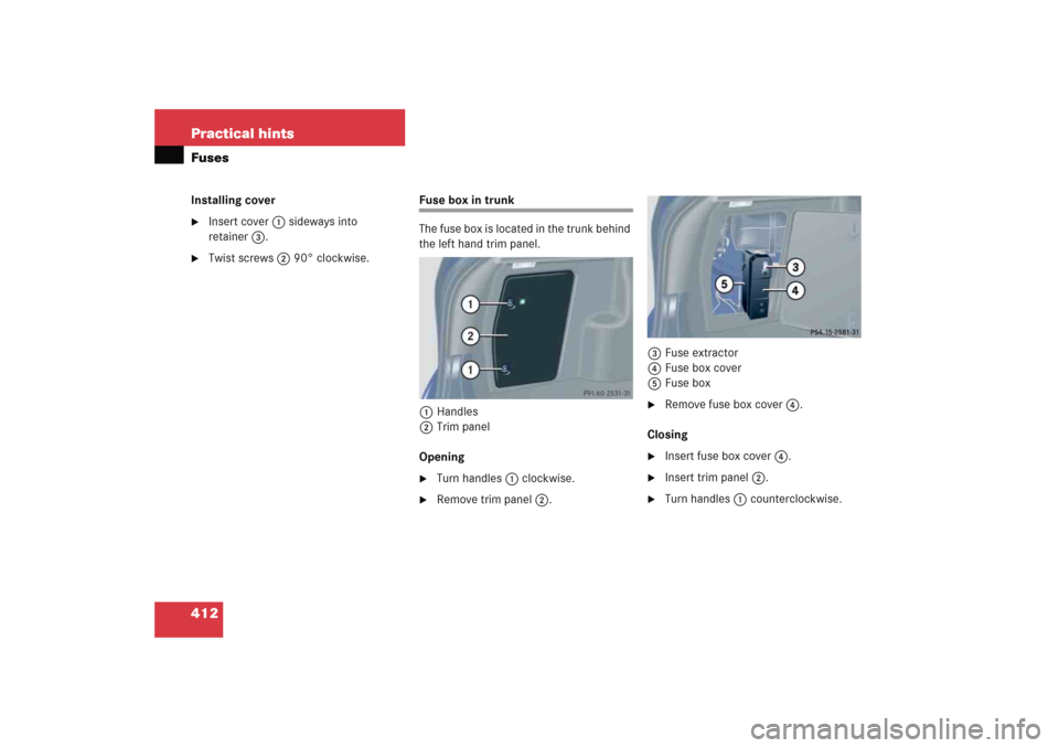
Fuse box in trunk
The fuse box is located in the trunk behind
the left hand trim panel.
1Handles
2Trim panel
Opening�
Turn handles1 clockwise.
�
Remove trim panel2.3Fuse extractor
4Fuse box cover
5Fuse box
�
Remove fuse box cover4.
Closing
�
Insert fuse box cover4.
�
Insert trim panel2.
�
Turn handles1 counterclockwise.