Page 375 of 474

374 Practical hintsWhere will I find ...?Vehicle jack
Storage position�
Remove the vehicle jack from the spare
wheel well under the trunk floor.
�
Push the crank handle up.
�
Turn the crank handle clockwise until it
engages (operational position).
Before storing the vehicle jack in its com-
partment:
�
It should be fully collapsed.
�
The handle must be folded in (storage
position).
Warning!
G
The jack is designed exclusively for jacking
up the vehicle at the jack take-up brackets
built into both sides of the vehicle. To help
avoid personal injury, use the jack only to lift
the vehicle during a wheel change. Never
get beneath the vehicle while it is supported
by the jack. Keep hands and feet away from
the area under the lifted vehicle. Always
firmly set parking brake and block wheels
before raising vehicle with jack.
Do not disengage parking brake while the
vehicle is raised. Be certain that the jack is
always vertical (plumb line) when in use, es-
pecially on hills. Always try to use the jack
on level surface. Make sure the jack arm is
fully seated in the jack take-up bracket. Al-
ways lower the vehicle onto sufficient ca-
pacity jack stands before working under the
vehicle.
Page 376 of 474
375 Practical hints
Where will I find ...?
Setting up the collapsible wheel chock
The collapsible wheel chock serves to ad-
ditionally secure the vehicle, e.g. while
changing the wheel.
1Tilt the plates upward
2Fold the lower plate outward
3Insert the plate
�
Tilt both plates upward1.
�
Fold the lower plate outward2.
�
Guide the tabs of the lower plate all the
way into the openings of the base
plate3.
Spare wheel
The spare wheel is located under the trunk
floor.
Removing the spare wheel�
Lift trunk floor.
1Spare wheel
2Storage tray with vehicle tool kit
3Mounting screw for spare wheel/cover
for vehicle tools
�
Turn the mounting screw3 counter-
clockwise.
�
Remove the spare wheel1.
Page 377 of 474

376 Practical hintsWhere will I find ...?Storing the spare wheel
If you wish to store the spare wheel after
use, carry out the following steps. Other-
wise the spare wheel will not fit the wheel
well.�
Unscrew the valve cap from the valve
of the spare wheel.
�
Carefully push the tip of the valve cap
into the spare wheel valve and allow
the air to escape.
�
Screw the valve cap back on the valve.
�
Place spare wheel1 in wheel well.
�
Turn retaining screw3 clockwise to
its stop to secure the spare wheel.
�
Install the trunk floor.Spare wheel bolts
1Wheel bolt for light alloy rims
2Wheel bolt for light alloy spare wheel
rim size 4
1/2B x15 H2For more information on model and spare
wheel rim size, see “Technical data”
section (
�page 422).
iIt may take a few minutes for the col-
lapsible tire to deflate completely.
!Wheel bolts2 must be used when
mounting spare wheel rim
size 4
1/2Bx15 H2 (
�page 422).
The use of any wheel bolts other than
wheel bolts2 for spare wheel rim
size 4
1/2B x15 H2 can cause physical
damage to the vehicle.
Warning!
G
Make sure to use the original length wheel
bolts when remounting the original wheel af-
ter it has been repaired.
Page 378 of 474
377 Practical hints
Unlocking/locking in an emergency
�Unlocking/locking in an emergency
Unlocking the vehicle
If you are unable to unlock the vehicle with
the SmartKey, open the driver’s door using
the mechanical key and the trunk lid using
the emergency release lever.
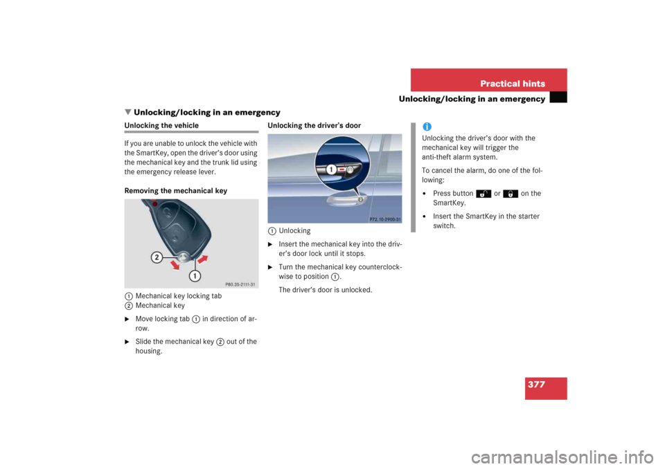
Removing the mechanical key
1Mechanical key locking tab
2Mechanical key�
Move locking tab1 in direction of ar-
row.
�
Slide the mechanical key2 out of the
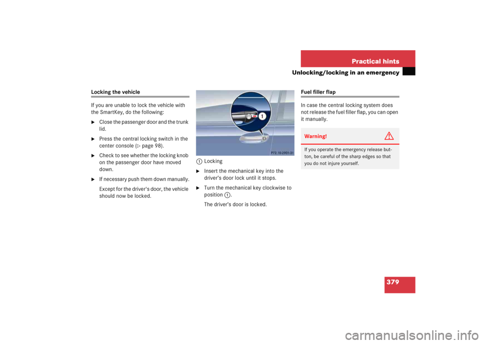
housing.Unlocking the driver’s door
1Unlocking
�
Insert the mechanical key into the driv-
er’s door lock until it stops.
�
Turn the mechanical key counterclock-
wise to position1.
The driver’s door is unlocked.
iUnlocking the driver’s door with the
mechanical key will trigger the
anti-theft alarm system.
To cancel the alarm, do one of the fol-
lowing:�
Press buttonŒ or ‹ on the
SmartKey.
�
Insert the SmartKey in the starter
switch.
Page 380 of 474
379 Practical hints
Unlocking/locking in an emergency
Locking the vehicle
If you are unable to lock the vehicle with
the SmartKey, do the following:�
Close the passenger door and the trunk
lid.
�
Press the central locking switch in the
center console (
�page 98).
�
Check to see whether the locking knob
on the passenger door have moved
down.
�
If necessary push them down manually.
Except for the driver's door, the vehicle
should now be locked.1Locking
�
Insert the mechanical key into the
driver’s door lock until it stops.
�
Turn the mechanical key clockwise to
position1.
The driver’s door is locked.
Fuel filler flap
In case the central locking system does
not release the fuel filler flap, you can open
it manually.Warning!
G
If you operate the emergency release but-
ton, be careful of the sharp edges so that
you do not injure yourself.
Page 381 of 474
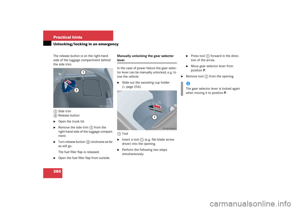
380 Practical hintsUnlocking/locking in an emergencyThe release button is on the right-hand
side of the luggage compartment behind
the side trim.
1Side trim
2Release button�
Open the trunk lid.
�
Remove the side trim1 from the
right-hand side of the luggage compart-
ment.
�
Turn release button2 clockwise as far
as will go.
The fuel filler flap is released.
�
Open the fuel filler flap from outside.Manually unlocking the gear selector
lever
In the case of power failure the gear selec-
tor lever can be manually unlocked, e.g. to
tow the vehicle.�
Slide out the swiveling cup holder
(�page 256).
1Tool
�
Insert a tool1 (e.g. flat blade screw
driver) into the opening.
�
Perform the following two steps
simultaneously:
�
Press tool1 forward in the direc-
tion of the arrow.
�
Move gear selector lever from
positionP.
�
Remove tool1 from the opening.iThe gear selector lever is locked again
when moving it to positionP.
Page 382 of 474
381 Practical hints
Opening/closing in an emergency
�Opening/closing in an emergency
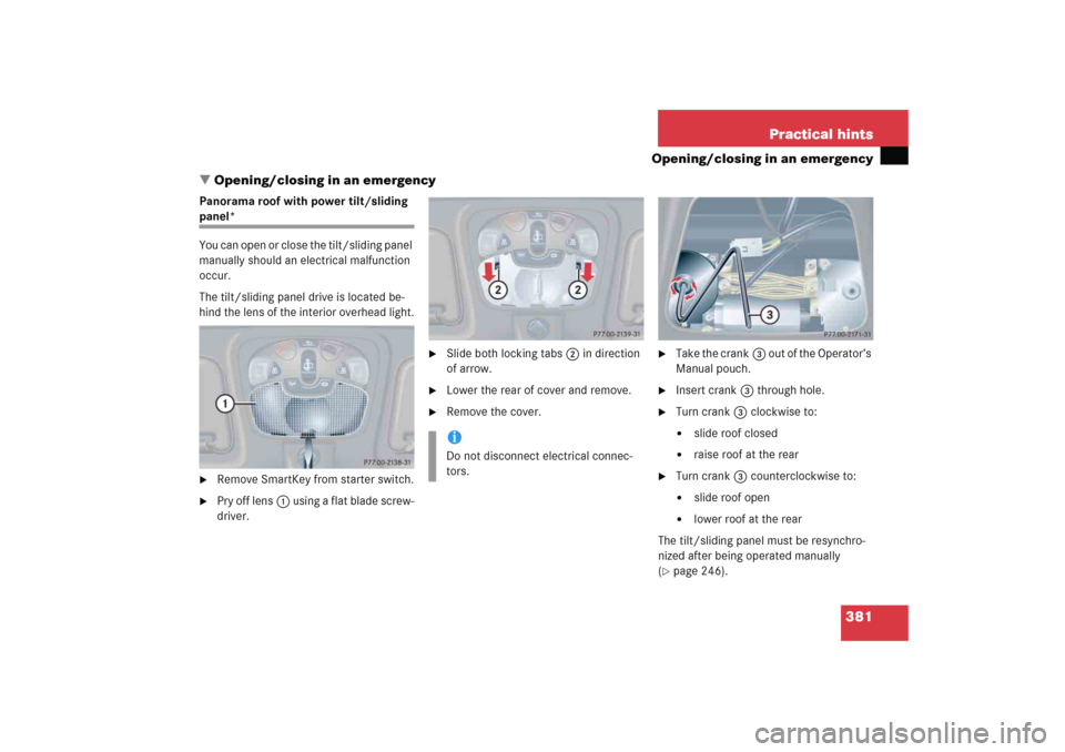
Panorama roof with power tilt/sliding panel*
You can open or close the tilt/sliding panel
manually should an electrical malfunction
occur.
The tilt/sliding panel drive is located be-
hind the lens of the interior overhead light.�
Remove SmartKey from starter switch.
�
Pry off lens1 using a flat blade screw-
driver.
�
Slide both locking tabs2 in direction
of arrow.
�
Lower the rear of cover and remove.
�
Remove the cover.
�
Take the crank3 out of the Operator’s
Manual pouch.
�
Insert crank3 through hole.
�
Turn crank3 clockwise to:�
slide roof closed
�
raise roof at the rear
�
Turn crank3 counterclockwise to:�
slide roof open
�
lower roof at the rear
The tilt/sliding panel must be resynchro-
nized after being operated manually
(
�page 246).
iDo not disconnect electrical connec-
tors.
Page 388 of 474

387 Practical hints
Replacing bulbs
3Bulb socket for turn signal lamp bulb
4Bulb holder of low beam bulb
5Bulb holder of high beam bulb
6Bulb socket for parking and standing
lamp bulbLow beam bulb
�
Turn housing cover1 counterclock-
wise and remove it.
�
Turn bulb holder4 with the bulb coun-
terclockwise and remove it.
�
Pull the bulb at its socket out of bulb
holder4.
�
Insert the new bulb so that its socket
locates in the recess of bulb holder4
and is level to it.
�
Reinsert bulb holder4 with the bulb in
the lamp and turn clockwise.
�
Align housing cover1 and turn it
clockwise.High beam bulb
�
Turn housing cover2 counterclock-
wise and remove it.
�
Turn bulb holder5 with the bulb coun-
terclockwise and remove it.
�
Pull the bulb at its socket out of bulb
holder5.
�
Insert the new bulb so that its socket
locates in the recess of bulb holder5
and is level to it.
�
Reinsert bulb holder5 w i t h t h e b u l b i n
the lamp and turn clockwise.
�
Align housing cover2 and turn it
clockwise.