Page 379 of 474
378 Practical hintsUnlocking/locking in an emergencyUnlocking and opening the trunk lid
A minimum height clearance of 7.1 ft.
(2.16 m) is required to open the trunk lid.
The emergency release is located on the
inside of the trunk lid.1 Cover
2 Emergency release lever
3 Rear bench seat backrest
�
Fold backrest 3 forward
(�page 251).
�
Remove cover 1 from the trim on the
trunk lid.
�
Push release lever 2 all the way to the
right.
The trunk lid unlocks.
�
Lift the trunk lid.!Always make sure there is sufficient
overhead clearance.
iIf the vehicle has previously been
locked from the outside with the
SmartKey, opening the trunk from the
inside using the emergency release le-
ver will trigger the anti-theft alarm sys-
tem*.
To cancel the alarm, do one of the fol-
lowing:�
Press button Œ or ‹ on the
SmartKey.
�
Insert the SmartKey in the starter
switch.
Page 380 of 474
379
Practical hints
Unlocking/locking in an emergency
Locking the vehicle
If you are unable to lock the vehicle with
the SmartKey, do the following:�
Close the passenger door and the trunk
lid.
�
Press the central locking switch in the
center console (
�page 98).
�
Check to see whether the locking knob
on the passenger door have moved
down.
�
If necessary push them down manually.
Except for the driver's door, the vehicle
should now be locked.
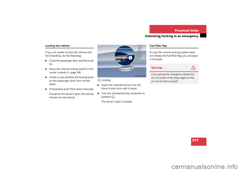
1
Locking
�
Insert the mechanical key into the
driver’s door lock until it stops.
�
Turn the mechanical key clockwise to
position 1.
The driver’s door is locked.
Fuel filler flap
In case the central locking system does
not release the fuel filler flap, you can open
it manually.Warning!
G
If you operate the emergency release but-
ton, be careful of the sharp edges so that
you do not injure yourself.
Page 381 of 474
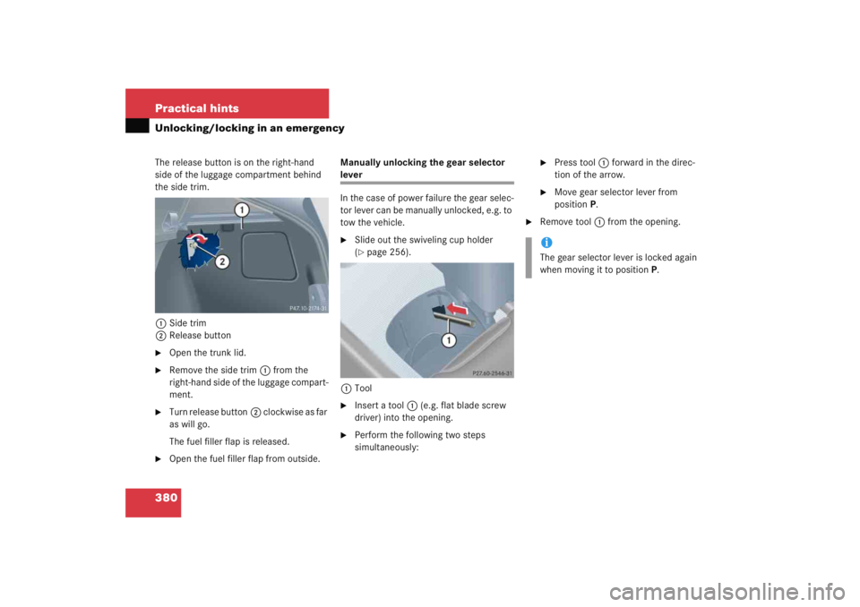
380 Practical hintsUnlocking/locking in an emergencyThe release button is on the right-hand
side of the luggage compartment behind
the side trim.1 Side trim
2 Release button�
Open the trunk lid.
�
Remove the side trim 1 from the
right-hand side of the luggage compart-
ment.
�
Turn release button 2 clockwise as far
as will go.
The fuel filler flap is released.
�
Open the fuel filler flap from outside. Manually unlocking the gear selector
lever
In the case of power failure the gear selec-
tor lever can be manually unlocked, e.g. to
tow the vehicle.�
Slide out the swiveling cup holder
(�page 256).
1 Tool
�
Insert a tool 1 (e.g. flat blade screw
driver) into the opening.
�
Perform the following two steps
simultaneously:
�
Press tool 1 forward in the direc-
tion of the arrow.
�
Move gear selector lever from
position P.
�
Remove tool 1 from the opening.iThe gear selector lever is locked again
when moving it to position P.
Page 391 of 474

390 Practical hintsReplacing bulbsParking and standing lamp bulb�
Turn housing cover2 counterclock-
wise and remove it.
�
Pull out bulb socket 5 with the bulb.
�
Pull the bulb out of bulb socket 5.
�
Press the new bulb into bulb socket 5.
�
Press bulb socket 5 back into the
lamp.
�
Align housing cover 2 and turn it
clockwise. Side marker lamp bulb
�
Carefully slide the lamp towards the
rear in direction of arrows.
�
Remove the front end first.
�
Turn the bulb socket with the bulb
counterclockwise and remove it.
�
Pull the bulb out of the bulb socket.
�
Insert the new bulb into the bulb sock-
et.
�
Place the bulb socket back into the
lamp and turn it clockwise.
�
To reinstall the lamp, set the rear end in
the bumper and let the front end en-
gage.
Replacing bulbs for rear lamps
Before you start to replace a bulb for a rear
lamp, do the following first:�
Turn the exterior lamp switch to
position
M (
�page 110).
Tail lamp unit
1 Trim panel
2 Latch
�
Open the trunk lid.
�
Turn latches 1 on respective trim
panel 2 clockwise.
�
Fold trim panel 2 to the side.
Page 392 of 474

391
Practical hints
Replacing bulbs
3
Tab
4 Bulb socket for side marker lamp bulb�
Press tabs 3 together.
�
Remove the bulb carrier.
�
Press gently onto the respective bulb
and turn counterclockwise out of its
bulb socket.
�
Press the new bulb gently into its bulb
socket and turn clockwise until it en-
gages. 5
Brake lamp bulb
6 Backup lamp bulb
7 Turn signal lamp bulb
8 Rear fog lamp bulb (only driver’s side),
tail, parking and standing lamp
�
Reinstall the bulb carrier.
Let tabs 3 engage.
�
Reinstall trim panel 2.
�
Turn latches 1 counterclockwise. Side marker lamp
The bulb socket for the side marker lamp
bulb is located between the bulb carrier
and the vehicle’s body.
�
Open the trunk lid.
�
Turn latches
1 on respective trim
panel 2 clockwise.
�
Fold trim panel 2 to the side.
�
Pull bulb socket 4 with the bulb out of
its holder.
�
Pull the bulb out of bulb socket 4.
�
Press the new bulb into bulb socket 4.
�
Press bulb socket 4 back into its
holder.
�
Reinstall trim panel 2.
�
Turn latches 1 counterclockwise.
Page 395 of 474

394 Practical hintsFlat tire
Preparing the vehicle�
Park the vehicle as far as possible from
moving traffic on a hard surface.
�
Turn on the hazard warning flashers.
�
Turn the steering wheel so that the
front wheels are in a straight ahead
position.
�
Move the gear selector lever toP
(manual transmission to first or reverse
gear).
�
Turn off the engine (
�page 58).
�
Remove the SmartKey from the starter
switch.
�
Have any passenger exit the vehicle at
a safe distance from the roadway.
Mounting the spare wheel
Preparing the vehicle
Prepare the vehicle as described
(�page 394).
�
Take the wheel wrench and the jack
out of wheel well below the trunk floor
(�page 373).
�
Take the spare wheel out of the trunk
(�page 375).
Warning!
G
The dimensions of the spare wheel are dif-
ferent from those of the road wheels. As a
result, the vehicle handling characteristics
change when driving with a spare wheel
mounted. Adapt your driving style accord-
ingly.
The spare wheel is for temporary use only.
When driving with spare wheel mounted, en-
sure proper tire pressure and do not exceed
vehicle speed of 50 mph (80 km/h).
Drive to the nearest Mercedes-Benz Center
as soon as possible to have the spare wheel
replaced with a regular road wheel.
Never operate the vehicle with more than
one spare wheel mounted.
Page 399 of 474
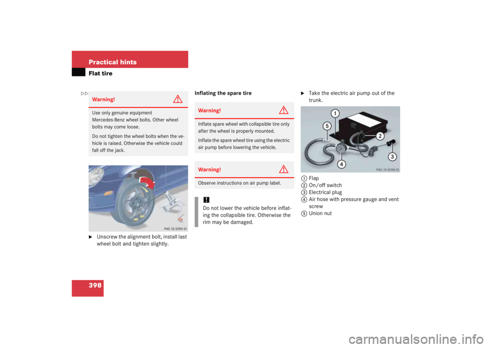
398 Practical hintsFlat tire�
Unscrew the alignment bolt, install last
wheel bolt and tighten slightly.Inflating the spare tire
�
Take the electric air pump out of the
trunk.
1 Flap
2 On/off switch
3 Electrical plug
4 Air hose with pressure gauge and vent
screw
5 Union nut
Warning!
G
Use only genuine equipment
Mercedes-Benz wheel bolts. Other wheel
bolts may come loose.
Do not tighten the wheel bolts when the ve-
hicle is raised. Otherwise the vehicle could
fall off the jack.
Warning!
G
Inflate spare wheel with collapsible tire only
after the wheel is properly mounted.
Inflate the spare wheel tire using the electric
air pump before lowering the vehicle.Warning!
G
Observe instructions on air pump label.!Do not lower the vehicle before inflat-
ing the collapsible tire. Otherwise the
rim may be damaged.
��
Page 400 of 474

399
Practical hints
Flat tire
�
Open flap
1 on electric air pump.
�
Pull out electrical plug 3 and air hose
with pressure gauge 4.
�
Remove the valve cap from valve.
�
Screw air hose 4 onto the tire valve.
�
Insert electrical plug 3 into vehicle
cigarette lighter socket.
�
Turn the SmartKey in the starter switch
to position 1.
�
Press I on electric air pump switch 2.
The electric air pump should now
switch on and inflate the spare tire.
�
Inflate the spare tire to approximately
36 psi (2.5 bar).
This takes about five minutes for the
spare tire. Air hose 4 and union
nut 5 can become hot during infla-
tion. Exercise proper caution to avoid
burning yourself when using the equip-
ment.
�
Press 0on electric air pump switch 2.
�
Turn the SmartKey in the starter switch
to position 0.
�
If the tire pressure is above 36 psi
(2.5 bar), release excess tire pressure
using the vent screw.
�
Detach the electric air pump.
�
Store the electrical plug and the air
hose behind the flap and place the air
pump back in the trunk.
!Do not operate the electric air pump
longer than six minutes without
interruption. Otherwise it may over-
heat.
You may operate the electric air pump
again after it has cooled off.
Warning!
G
Follow recommended inflation pressures.
Do not overinflate tires. Overinflated tires
can result in sudden deflation (blowout) be-
cause they are more likely to become punc-
tured or damaged by road debris, potholes,
etc.
Do not underinflate tires. Underinflated tires
wear unevenly, adversely affect handling
and fuel economy, and are more likely to fail
from being overheated.
 is required to open the trunk lid.
The emergency release is loca")