Page 397 of 474

396 Practical hintsFlat tireThe jack take-up brackets are located
directly behind the front wheel housings
and in front of the rear wheel housings.1 Jack
2 Crank
3 Take-up bracket�
Place jack on firm ground.
�
Position jack 1 under the take-up
bracket 3 so that it is always vertical
(plumb-line) as seen from the side,
even if the vehicle is parked on an
incline.
�
Jack up the vehicle until the wheel is a
maximum of 1.2 in (3 cm) from the
ground. Never start engine while vehi-
cle is raised. Removing the wheel
1 Alignment bolt
�
Unscrew upper-most wheel bolt and
remove.
�
Replace this wheel bolt with the align-
ment bolt 1 supplied in the tool kit.
�
Remove the remaining bolts.
�
Remove the wheel.
Warning!
G
The jack is intended only for lifting the
vehicle briefly for wheel changes. It is not
suited for performing maintenance work un-
der the vehicle.�
Never start the engine when the vehicle
is raised.
�
Never lie down under the raised vehicle.
!Do not place wheel bolts in sand or dirt.
This could result in damage to the bolt
and wheel hub threads.
Page 398 of 474

397
Practical hints
Flat tire
Mounting the spare wheel
1 Wheel bolt for light alloy rims
2 Wheel bolt for light alloy spare wheel
rim size 4
1/2B x15 H2
�
Clean contact surfaces of wheel and
wheel hub.
�
Guide the spare wheel onto the align-
ment bolt and push it on.
�
Insert wheel bolts and tighten them
slightly.
�
Inflate the spare tire using the electric
air pump (
�page 398).
!Wheel bolts 2 must be used when
mounting spare wheel rim
size 4
1/2Bx15 H2 (
�page 422).
The use of any wheel bolts other than
wheel bolts 2 for spare wheel rim
size 4
1/2B x15 H2 can cause physical
damage to the vehicle.
!To avoid paint damage, place wheel flat
against hub and hold it there while
installing first wheel bolt.Warning!
G
Always replace wheel bolts that are dam-
aged or rusted.
Never apply oil or grease to wheel bolts.
Damaged wheel hub threads should be re-
paired immediately. Do not continue to drive
under these circumstances! Contact an
authorized Mercedes-Benz Center or call
Roadside Assistance.
Incorrect wheel bolts or improperly tight-
ened wheel bolts can cause the wheel to
come off. This could cause an accident.
Make sure to use the correct mounting
bolts.
Warning!
G
Inflate spare wheel with collapsible tire only
after the wheel is properly mounted.
Inflate the spare wheel tire using the electric
air pump before lowering the vehicle.
��
Page 399 of 474
398 Practical hintsFlat tire�
Unscrew the alignment bolt, install last
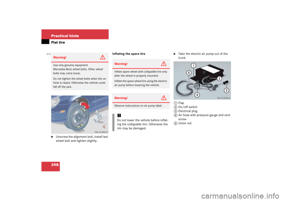
wheel bolt and tighten slightly.Inflating the spare tire
�
Take the electric air pump out of the
trunk.
1 Flap
2 On/off switch
3 Electrical plug
4 Air hose with pressure gauge and vent
screw
5 Union nut
Warning!
G
Use only genuine equipment
Mercedes-Benz wheel bolts. Other wheel
bolts may come loose.
Do not tighten the wheel bolts when the ve-
hicle is raised. Otherwise the vehicle could
fall off the jack.
Warning!
G
Inflate spare wheel with collapsible tire only
after the wheel is properly mounted.
Inflate the spare wheel tire using the electric
air pump before lowering the vehicle.Warning!
G
Observe instructions on air pump label.!Do not lower the vehicle before inflat-
ing the collapsible tire. Otherwise the
rim may be damaged.
��
Page 401 of 474
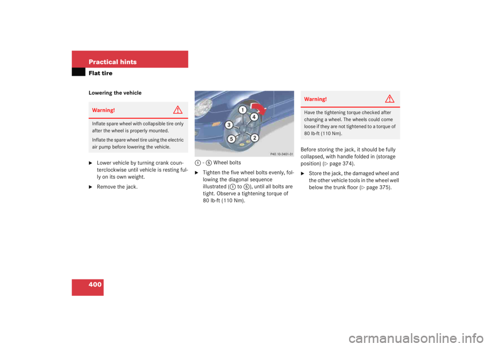
400 Practical hintsFlat tireLowering the vehicle�
Lower vehicle by turning crank coun-
terclockwise until vehicle is resting ful-
ly on its own weight.
�
Remove the jack.1
-5 Wheel bolts
�
Tighten the five wheel bolts evenly, fol-
lowing the diagonal sequence
illustrated ( 1 to 5 ), until all bolts are
tight. Observe a tightening torque of
80 lb-ft (110 Nm). Before storing the jack, it should be fully
collapsed, with handle folded in (storage
position) (
�page 374).
�
Store the jack, the damaged wheel and
the other vehicle tools in the wheel well
below the trunk floor (
�page 375).
Warning!
G
Inflate spare wheel with collapsible tire only
after the wheel is properly mounted.
Inflate the spare wheel tire using the electric
air pump before lowering the vehicle.
Warning!
G
Have the tightening torque checked after
changing a wheel. The wheels could come
loose if they are not tightened to a torque of
80 lb-ft (110 Nm).
Page 407 of 474

406 Practical hintsTowing the vehicleMercedes-Benz recommends that the vehi-
cle be transported with all wheels off the
ground using flatbed or appropriate wheel
lift/dolly equipment. This method is pref-
erable to other types of towing.When circumstances do not permit the
recommended towing methods, the vehi-
cle may be towed with all wheels on the
ground or front wheels raised only so far as
necessary to have the vehicle moved to a
safe location where the recommended
towing methods can be employed.
!Use flatbed or wheel lift/dolly equip-
ment with SmartKey in starter switch
turned to position
0.
Do not tow with sling-type equipment.
Towing with sling-type equipment over
bumpy roads will damage radiator and
supports.
To prevent damage during transport,
do not tie down vehicle by its chassis or
suspension parts.
Switch off the tow-away alarm
(�page 87) and deactivate the auto-
matic central locking (
�page 148).
!Vehicles with automatic transmission:
Do not tow-start the vehicle.
!If the vehicle is towed with the front
axle raised, the engine must be shut off
(SmartKey in starter switch position 0
or 1). Otherwise, the ESP will immedi-
ately be engaged and will apply the rear
wheel brakes.
When towing the vehicle with all wheels
on the ground, the gear selector lever
must be in position N (manual trans-
mission: gears disengaged) and the
SmartKey must be in starter switch
position 2.
When towing the vehicle with all wheels
on the ground or the front axle raised,
the vehicle may be towed only for dis-
tances up to 30 miles (50 km) and at a
speed not to exceed 30 mph
(50 km/h).
Page 408 of 474

407
Practical hints
Towing the vehicle
!
To be certain to avoid a possibility of
damage to the transmission, however,
we recommend the drive shaft be dis-
connected at the rear axle drive flange
for any towing beyond a short tow to a
nearby garage.
Warning!
G
If circumstances require towing the vehicle
with all wheels on the ground, always tow
with a tow bar if:�
the engine will not run
�
there is a malfunction in the power sup-
ply or in the vehicle’s electrical system
as that will be necessary to adequately con-
trol the towed vehicle.
Prior to towing the vehicle with all wheels on
the ground, make sure the SmartKey is in
starter switch position 2.
If the SmartKey is left in starter switch
position 0 for an extended period of time, it
can no longer be turned in the switch. In this
case, the steering is locked. To unlock, re-
move SmartKey from starter switch and re-
insert.
iTo signal turns while being towed with
the hazard warning flasher in use, turn
SmartKey in starter switch to
position 2 and activate the combina-
tion switch for the left or right turn sig-
nal in the usual manner – only the
selected turn signal will operate.
Upon canceling the turn signal, the
hazard warning flasher will operate
again.
Page 409 of 474

408 Practical hintsTowing the vehicleWarning!
G
With the engine not running, there is no
power assistance for the brake and steering
systems. In this case, it is important to keep
in mind that a considerably higher degree of
effort is necessary to brake and steer the ve-
hicle. Adapt your driving accordingly.
!When towing the vehicle with all wheels
on the ground, please note the follow-
ing:
With the automatic central locking acti-
vated and the SmartKey in starter
switch position2, the vehicle doors
lock if the left front wheel as well as the
right rear wheel are turning at vehicle
speeds of approximately 9 mph
(15 km/h) or more.
Switch off the tow-away alarm
(�page 87).
To prevent the vehicle doors from lock-
ing, deactivate the automatic central
locking (
�page 148).
Towing of the vehicle should only be
done using the properly installed tow-
ing eye bolt. Never attach tow cable,
tow rope or tow rod to vehicle chassis,
frame or suspension parts.
iIf the battery is disconnected or dis-
charged�
the SmartKey will not turn in the
starter switch. For more informa-
tion, see “Battery” (
�page 401)
and “Jump starting” (�page 404).
�
the gear selector lever will remain
locked in position P. For informa-
tion on manually unlocking trans-
mission gear selector lever, see
(�page 380).
Page 410 of 474
409
Practical hints
Towing the vehicle
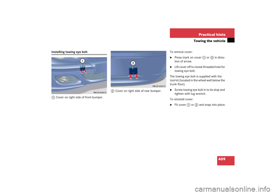
Installing towing eye bolt
1 Cover on right side of front bumper. 2
Cover on right side of rear bumper. To remove cover:
�
Press mark on cover
1 or 2 in direc-
tion of arrow.
�
L i f t c o v e r o f f t o r e v e a l t h r e a d e d h o l e f o r
towing eye bolt.
The towing eye bolt is supplied with the
tool kit (located in the wheel well below the
trunk floor).
�
Screw towing eye bolt in to its stop and
tighten with lug wrench.
To reinstall cover:
�
Fit cover 1 or 2 and snap into place.