Page 34 of 474

33
Getting started
Unlocking
Starter switch positions
Starter switch0
For removing SmartKey
The steering is locked when the Smart-
Key is removed from the starter switch.
If necessary, move steering wheel
slightly to allow the locking mechanism
to engage.
1 Power supply to some electrical con-
sumers, such as seat adjustment 2
Ignition (power supply for all electrical
consumers) and driving position. All
lamps (except low beam headlamp in-
dicator lamp, high beam headlamp indi-
cator lamp, and turn signal indicator
lamps unless activated) in the instru-
ment cluster come on. If a lamp in the
instrument cluster fails to come on
when the ignition is switched on, have
it checked and replaced if necessary. If
a lamp in the instrument cluster re-
mains on after starting the engine or
comes on while driving, refer to “Lamps
in instrument cluster” (
�page 340).
3 Starting position
Warning!
G
When leaving the vehicle, always remove the
SmartKey from the starter switch, take it
with you, and lock the vehicle. Do not leave
children unattended in the vehicle, or with
access to an unlocked vehicle. Unsuper-
vised use of vehicle equipment may cause
an accident and/or serious personal injury.
Page 35 of 474

34 Getting startedUnlocking
iWhen you switch on the ignition, the in-
dicator and warning lamps (except low
beam headlamp indicator lamp, high
beam headlamp indicator lamp, and
turn signal indicator lamps unless acti-
vated) in the instrument cluster come
on. This indicates that the respective
systems are operational. The indicator
and warning lamps (except low beam
headlamp indicator lamp, high beam
headlamp indicator lamp, and turn sig-
nal indicator lamps if activated) should
go out when the engine is running.iVehicles with automatic transmission:
The SmartKey can only be removed
from the starter switch with the gear
selector lever in positionP.
!If the SmartKey cannot be turned in the
starter switch, the battery may not be
sufficiently charged.�
Check the battery and charge it if
necessary (
�page 401).
�
Get a jump start (
�page 404).
To prevent accelerated battery dis-
charge and a possible dead battery, al-
ways remove the SmartKey from the
starter switch when the engine is not in
operation.
Page 39 of 474

38 Getting startedAdjustingPower seat* adjustment
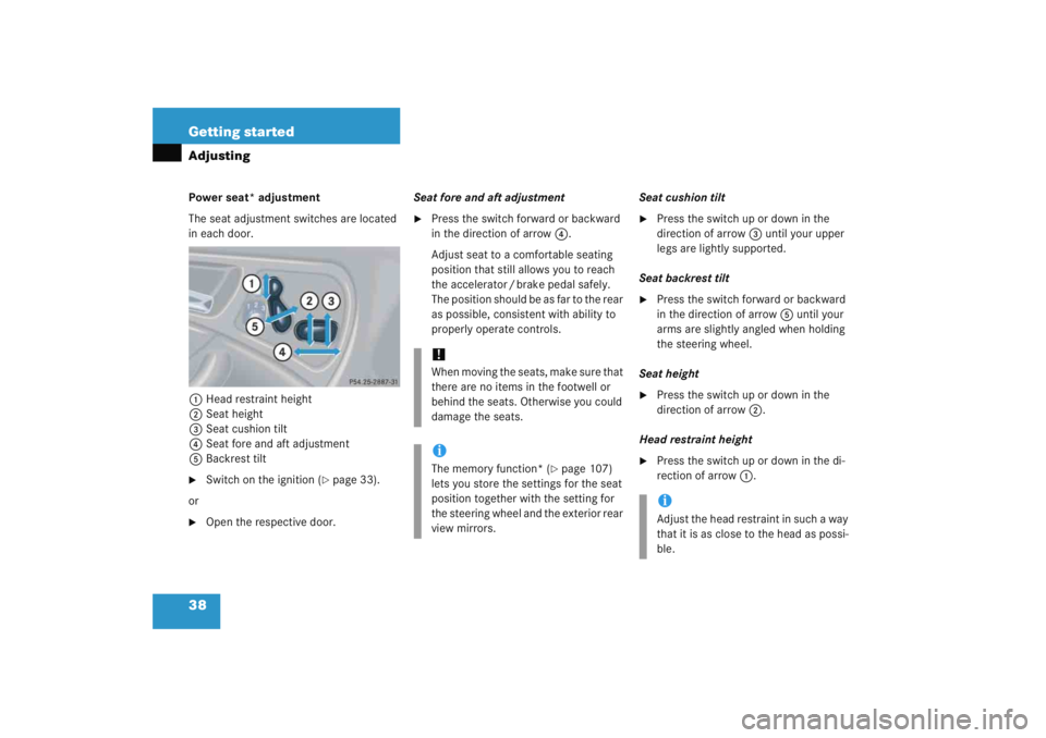
The seat adjustment switches are located
in each door.1 Head restraint height
2 Seat height
3 Seat cushion tilt
4 Seat fore and aft adjustment
5 Backrest tilt�
Switch on the ignition (
�page 33).
or
�
Open the respective door. Seat fore and aft adjustment
�
Press the switch forward or backward
in the direction of arrow
4.
Adjust seat to a comfortable seating
position that still allows you to reach
the accelerator / brake pedal safely.
The position should be as far to the rear
as possible, consistent with ability to
properly operate controls. Seat cushion tilt
�
Press the switch up or down in the
direction of arrow
3 until your upper
legs are lightly supported.
Seat backrest tilt
�
Press the switch forward or backward
in the direction of arrow 5 until your
arms are slightly angled when holding
the steering wheel.
Seat height
�
Press the switch up or down in the
direction of arrow 2.
Head restraint height
�
Press the switch up or down in the di-
rection of arrow 1.
!W h e n m o v i n g t h e s e a t s , m a k e s u r e t h a t
there are no items in the footwell or
behind the seats. Otherwise you could
damage the seats.iThe memory function* (
�page 107)
lets you store the settings for the seat
position together with the setting for
the steering wheel and the exterior rear
view mirrors.
iAdjust the head restraint in such a way
that it is as close to the head as possi-
ble.
Page 42 of 474

41
Getting started
Adjusting
Steering wheel adjustment, manual
1 Handle�
To unlock the steering column, pull
handle 1 out until its stop limit.
�
Move steering wheel to the desired
position.
�
To lock the steering column, push
handle 1 all the way in until it
engages.
The steering wheel is once again
locked into position.
�
Make sure the steering wheel is
securely locked by trying to move it up
and down, and in and out before driving
off.
Make sure your legs can move freely and
that all the displays (inclusive malfunction
and indicator lamps) on the instrument
cluster are clearly visible. Steering wheel adjustment, electrical*
The stalk for steering wheel adjustment is
located on the steering column (lower left).
1 Adjusting steering column, in or out
2 Adjusting steering column, up or down
�
Switch on the ignition (
�page 33).
or
�
Open the driver’s door.
Warning!
G
Only adjust the steering wheel with the vehi-
cle at a standstill and make sure the steer-
ing wheel is securely locked in place before
driving off.
Driving without the steering wheel adjust-
ment locked may cause an unexpected
steering wheel movement which could
cause the driver to lose control of the vehi-
cle. Make sure the steering wheel is secure-
ly locked by trying to move it up and down,
and in and out before driving off.
Page 44 of 474

43
Getting started
Adjusting
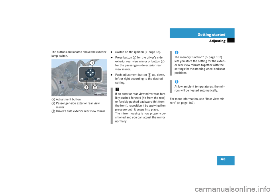
The buttons are located above the exterior
lamp switch.
1 Adjustment button
2 Passenger-side exterior rear view
mirror
3 Driver’s side exterior rear view mirror
�
Switch on the ignition (
�page 33).
�
Press button 3 for the driver’s side
exterior rear view mirror or button 2
for the passenger-side exterior rear
view mirror.
�
Push adjustment button 1 up, down,
left or right according to the desired
setting.
For more information, see “Rear view mir-
rors” (
�page 167).
!If an exterior rear view mirror was forc-
ibly pushed forward (hit from the rear)
or forcibly pushed backward (hit from
the front), reposition it by applying firm
pressure until it snaps into place.
The mirror housing is now properly po-
sitioned and you can adjust the mirror
normally.
iThe memory function* (
�page 107)
lets you store the setting for the exteri-
or rear view mirrors together with the
settings for the steering wheel and seat
positions.
iAt low ambient temperatures, the mir-
rors will be heated automatically.
Page 54 of 474

53
Getting started
Driving
Windshield wipers
The combination switch is located on the
left of the steering column.Combination switch1
Single wipe
2 Switching on windshield wipers �
Switch on the ignition (
�page 33). Switching on windshield wipers
�
Turn the combination switch to the
desired position depending on the
intensity of the rain.
0
Windshield wipers off
I Intermittent wiping
II Normal wiper speed
III Fast wiper speediVehicles without rain sensor*:
When the vehicle is standing still, the
wiper speed returns to the next lower
setting.
Vehicles with rain sensor*:
Intermittent wiping interval is depen-
dent on wetness of windshield. After
the initial wipe, pauses between wipes
are automatically controlled by the rain
sensor.
!Vehicles with rain sensor*:
Do not leave windshield wipers in inter-
mittent setting when the vehicle is tak-
en to an automatic car wash or during
windshield cleaning. Wipers will oper-
ate in the presence of water sprayed on
the windshield, and wipers may be
damaged as a result.
The switch should not be left in inter-
mittent setting as the wipers will wipe
the windshield once every time the
engine is started. Dust that accumu-
lates on the windshield might scratch
the glass and/or damage the wiper
blades when wiping occurs on a dry
windshield.
Page 56 of 474

55
Getting started
Driving
Problems while driving
The engine runs erratically and misfires�
An ignition cable may be damaged.
�
The engine electronics may not be
operating properly.
�
Unburned gasoline may have entered
the catalytic converter and damaged it.
�
Give very little gas.
�
Have the problem repaired by an
authorized Mercedes-Benz Center as
soon as possible.
The coolant temperature is over 248°F
(120°C)
The coolant is too hot and is no longer
cooling the engine.
�
Stop the vehicle as soon as possible
and turn off the engine. Allow engine
and coolant to cool.
�
Check the coolant level and add cool-
ant if necessary (
�page 296).
In case of accident
If the vehicle is leaking gasoline:
�
Do not start the engine under any cir-
cumstances.
�
Notify local fire and/or police authori-
ties.
If the extent of the damage cannot be
determined:
�
Notify an authorized Mercedes-Benz
Center.
If no damage can be determined on the
�
major assemblies
�
fuel system
�
engine mount:
�
Start the engine in the usual manner.
Page 61 of 474

60 Safety and SecurityOccupant safetyIn this section you will learn the most im-
portant facts about the restraint system
components of the vehicle.
Restraint system with�
Seat belts (
�page 66)
�
Child restraints (
�page 77)
�
Lower anchors and tethers for children
(LATCH) (
�page 78)
Supplemental Restraint System (SRS) with
�
Air bags (
�page 61)
�
Air bag control unit (with crash
sensors)
�
Emergency tensioning device (ETD) for
seat belts (
�page 69) Air bag system components with
�
56
indicator lamp (
�page 76)
�
Front passenger seat with Occupant
Classification System (OCS)
(�page 73)
As independent systems, their protective
functions work in conjunction with each
other. The SRS system conducts a self-test when
the ignition is switched on and in regular
intervals while the engine is running. This
facilitates early detection of malfunctions.
The
1 indicator lamp in the instrument
cluster comes on when the ignition is
switched on and goes out no later than a
few seconds after the engine has been
started.
The SRS components are in operational
readiness if the 1indicator lamp is not
lit when the engine is running.
A malfunction in the system has been
detected if the 1indicator lamp:
�
fails to go out after approximately four
seconds after the engine was started
�
does not come on at all
�
comes on after the engine was started
or while driving.
iFor information on infants and children
traveling with you in the vehicle and
restraint systems for infants and chil-
dren, see “Children in the vehicle”
(�page 70).