2005 LINCOLN TOWN CAR driver door panel
[x] Cancel search: driver door panelPage 138 of 328
A driver’s first responsibility is the safe operation of the vehicle.
The most important thing you can do to prevent a crash is to
avoid distractions and pay attention to the road. Wait until it is safe to
operate Mobile Communications Equipment.
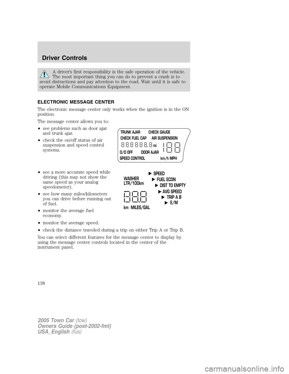
ELECTRONIC MESSAGE CENTER
The electronic message center only works when the ignition is in the ON
position.
The message center allows you to:
•see problems such as door ajar
and trunk ajar.
•check the on/off status of air
suspension and speed control
systems.
•see a more accurate speed while
driving (this may not show the
same speed as your analog
speedometer).
•see how many miles/kilometers
you can drive before running out
of fuel.
•monitor the average fuel
economy.
•monitor the average speed.
•check the distance traveled during a trip on either Trip A or Trip B.
You can select different features for the message center to display by
using the message center controls located in the center of the
instrument panel.
2005 Town Car(tow)
Owners Guide (post-2002-fmt)
USA_English(fus)
Driver Controls
138
Page 143 of 328
POWER TRUNK (IF EQUIPPED)
Your vehicle may be equipped with a power trunk controlled by the
interior trunk control, the key fob or the keypad on the door.
If anything obstructs the power trunk while it is closing, the trunk will
automatically reverse to the open position, provided it meets sufficient
resistance. Resistance must be as strong as the force of the closing
trunk, or stronger. The force of the closing trunk increases as the trunk
approaches the latched position. The trunk will close with the next press
of the interior trunk control or key fob button.
Make sure all persons are clear of the luggage compartment area
before using the power trunk control.
If the battery is disconnected, discharged, or a new battery is installed,
the power trunk needs to be reset. To reset the power trunk:
•Reconnect the battery with the trunk closed
•Power activate the trunk with the power interior trunk release, the
key fob or the keypad on the door to the full open position, then
power activate the same power source and fully close the trunk. The
power trunk is now reset.
INTERIOR TRUNK CONTROL
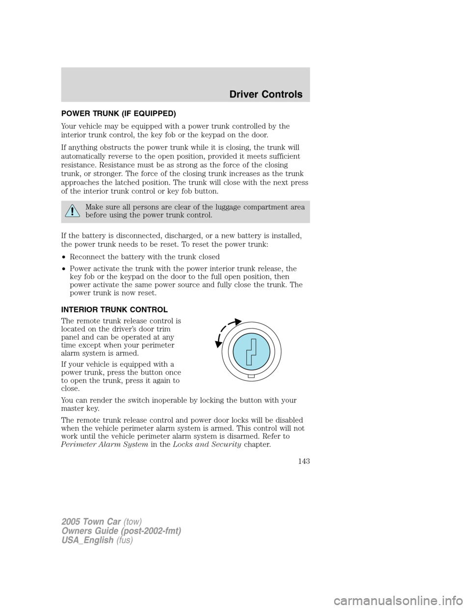
The remote trunk release control is
located on the driver’s door trim
panel and can be operated at any
time except when your perimeter
alarm system is armed.
If your vehicle is equipped with a
power trunk, press the button once
to open the trunk, press it again to
close.
You can render the switch inoperable by locking the button with your
master key.
The remote trunk release control and power door locks will be disabled
when the vehicle perimeter alarm system is armed. This control will not
work until the vehicle perimeter alarm system is disarmed. Refer to
Perimeter Alarm Systemin theLocks and Securitychapter.
2005 Town Car(tow)
Owners Guide (post-2002-fmt)
USA_English(fus)
Driver Controls
143
Page 155 of 328

Pressonce to unlock the driver’s door and move the memory features
to the corresponding memory position, just as if you had pressed the
memory control in the vehicle.
Activating the memory seat/mirrors/adjustable pedals feature
To activate this feature:
1. Position the seat, mirrors and
adjustable pedals to the position
desired.
2. Press the SET control on the
driver’s door panel.
3. Within five seconds, press one control on the remote transmitter and
then press the 1 or 2 button on the driver’s door panel to which you
would like to associate with the memory positions and Driver 1 or Driver
2 positions.
4. Repeat this procedure for another remote transmitter, if desired.
Deactivating the memory seat/mirrors/adjustable pedals feature
To deactivate this feature:
1. Press the SET control on the
driver’s door panel.
2. Within five seconds, press one
control on the remote transmitter
which you would like to deactivate
and then press the SET control on the driver’s door panel .
3. Repeat this procedure for another remote transmitter, if desired.
KEYLESS ENTRY SYSTEM (IF EQUIPPED)
You can use the keyless entry
keypad to:
•lock or unlock the doors without
using a key.
•open the trunk.
The keypad can be operated with the factory set 5–digit entry code; this
code is located on the owner’s wallet card in the glove box, is marked on
the computer module, and is available from your authorized dealer. You
can also create your own 5–digit personal entry code.
When pressing the controls on the keypad, press the middle of the
controls to ensure a good activation.
SET
12
SET
12
123
45678
90
2005 Town Car(tow)
Owners Guide (post-2002-fmt)
USA_English(fus)
Locks and Security
155
Page 166 of 328
The heated seat module resets at every ignition run cycle. While the
ignition is in the ON position, activating the high or low heated seat
switch enables heating mode. When activated, they will turn off
automatically when the ignition is turned to the OFF position.
The indicator light will illuminate when the heated seats have been
activated.
Rear heated seats (if equipped)
The rear seat heat controls are located on the rear door panels and
operate like the front heated seats. Refer to theHeated Seatssection in
this chapter for instructions on operating the rear heated seats.
Easy-access/easy-out feature (if equipped)
This feature automatically moves the driver’s seat backward when:
•the transmission is in N (Neutral) or P (Park)
•the key is removed from the ignition cylinder
The seat will move 2 inches (5 cm) forward (to the original position)
when:
•the transmission is in N (Neutral) or P (Park)
•the key is placed in the ignition cylinder
Seat mounted cup holders
Your vehicle may be equipped with cupholders in the cushion of the
front center seat and the rear seat . The rear seat cupholder is designed
to over rotate from the seat when subjected to a heavy load. The rear
seat cupholder can be reset by rotating to the closed position.
Use only soft cups in the cupholder. Hard objects can injure you
in a collision.
Memory seats/rearview mirrors/adjustable pedals (if equipped)
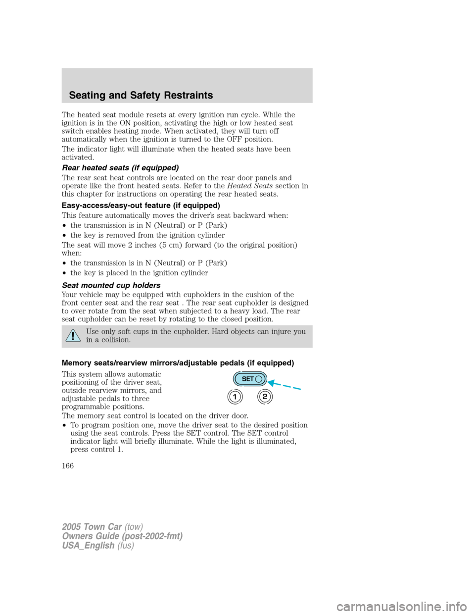
This system allows automatic
positioning of the driver seat,
outside rearview mirrors, and
adjustable pedals to three
programmable positions.
The memory seat control is located on the driver door.
•To program position one, move the driver seat to the desired position
using the seat controls. Press the SET control. The SET control
indicator light will briefly illuminate. While the light is illuminated,
press control 1.
SET
12
2005 Town Car(tow)
Owners Guide (post-2002-fmt)
USA_English(fus)
Seating and Safety Restraints
166
Page 191 of 328
Do not attempt to service, repair, or modify the air bag SRS, its
fuses or the seat cover on a seat containing an air bag. See your
Ford or Lincoln/Mercury dealer.
All occupants of the vehicle should always wear their safety belts
even when an air bag SRS is provided.
How does the side air bag system work?
The design and development of the
side airbag system included
recommended testing procedures
that were developed by a group of
automotive safety experts known as
the Side Airbag Technical Working
Group. These recommended testing
procedures help reduce the risk of
injuries related to the deployment of
side airbags.
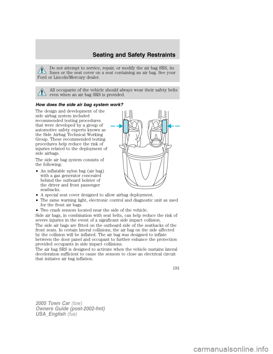
The side air bag system consists of
the following:
•An inflatable nylon bag (air bag)
with a gas generator concealed
behind the outboard bolster of
the driver and front passenger
seatbacks.
•A special seat cover designed to allow airbag deployment.
•The same warning light, electronic control and diagnostic unit as used
for the front air bags.
•Two crash sensors located near the side of the vehicle.
Side air bags, in combination with seat belts, can help reduce the risk of
severe injuries in the event of a significant side impact collision.
The side air bags are fitted on the outboard side of the seatbacks of the
front seats. In certain lateral collisions, the air bag on the side affected
by the collision will be inflated. The air bag was designed to inflate
between the door panel and occupant to further enhance the protection
provided occupants in side impact collisions.
The air bag SRS is designed to activate when the vehicle sustains lateral
deceleration sufficient to cause the sensors to close an electrical circuit
that initiates air bag inflation.
2005 Town Car(tow)
Owners Guide (post-2002-fmt)
USA_English(fus)
Seating and Safety Restraints
191
Page 256 of 328
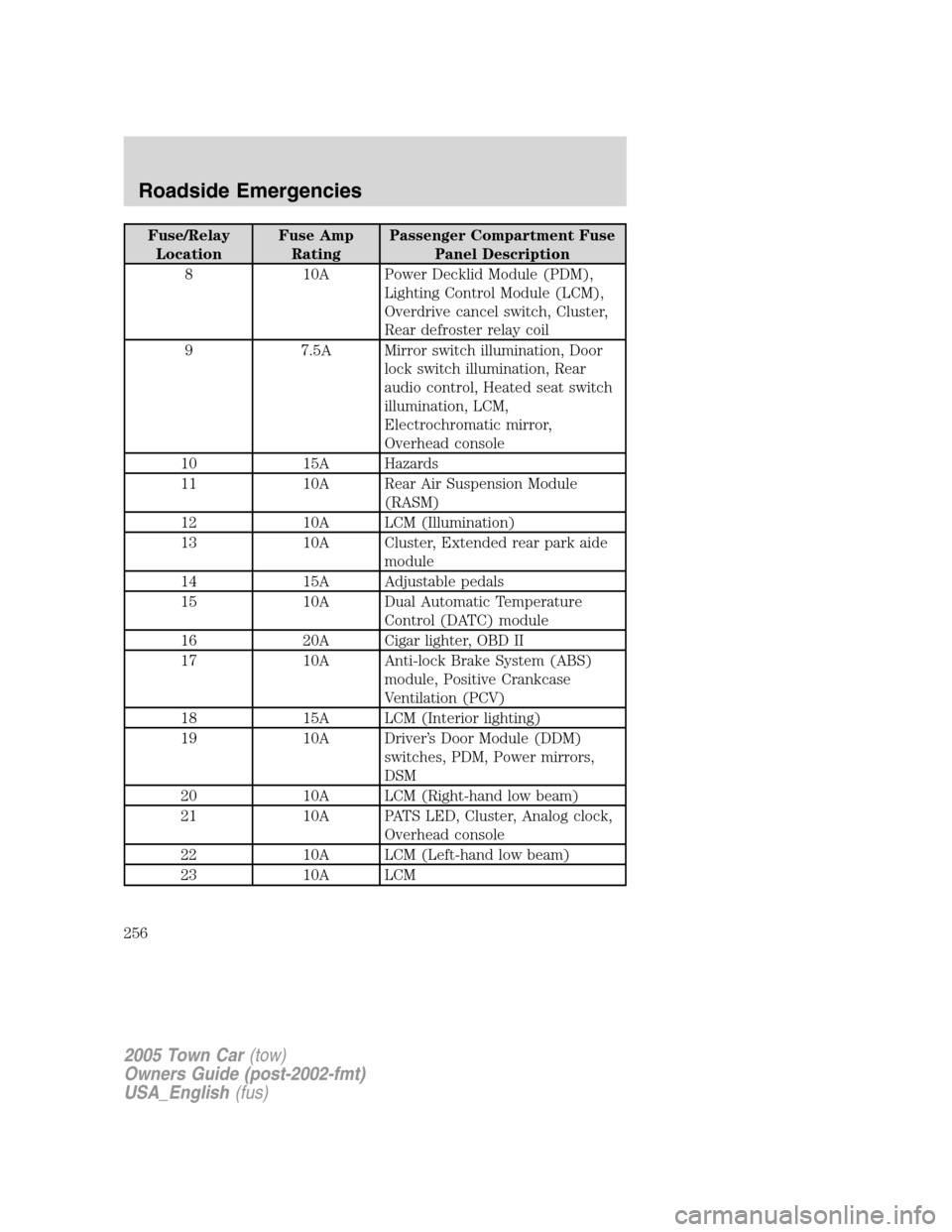
Fuse/Relay
LocationFuse Amp
RatingPassenger Compartment Fuse
Panel Description
8 10A Power Decklid Module (PDM),
Lighting Control Module (LCM),
Overdrive cancel switch, Cluster,
Rear defroster relay coil
9 7.5A Mirror switch illumination, Door
lock switch illumination, Rear
audio control, Heated seat switch
illumination, LCM,
Electrochromatic mirror,
Overhead console
10 15A Hazards
11 10A Rear Air Suspension Module
(RASM)
12 10A LCM (Illumination)
13 10A Cluster, Extended rear park aide
module
14 15A Adjustable pedals
15 10A Dual Automatic Temperature
Control (DATC) module
16 20A Cigar lighter, OBD II
17 10A Anti-lock Brake System (ABS)
module, Positive Crankcase
Ventilation (PCV)
18 15A LCM (Interior lighting)
19 10A Driver’s Door Module (DDM)
switches, PDM, Power mirrors,
DSM
20 10A LCM (Right-hand low beam)
21 10A PATS LED, Cluster, Analog clock,
Overhead console
22 10A LCM (Left-hand low beam)
23 10A LCM
2005 Town Car(tow)
Owners Guide (post-2002-fmt)
USA_English(fus)
Roadside Emergencies
256
Page 258 of 328
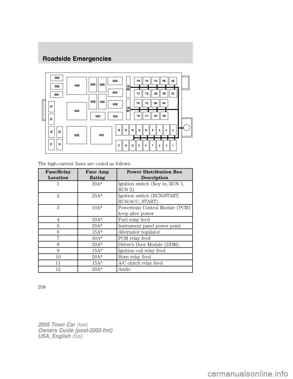
The high-current fuses are coded as follows.
Fuse/Relay
LocationFuse Amp
RatingPower Distribution Box
Description
1 20A* Ignition switch (Key in, RUN 1,
RUN 2)
2 25A* Ignition switch (RUN/START,
RUN/ACC, START)
3 10A* Powertrain Control Module (PCM)
keep alive power
4 20A* Fuel relay feed
5 20A* Instrument panel power point
6 15A* Alternator regulator
7 30A* PCM relay feed
8 20A* Driver’s Door Module (DDM)
9 15A* Ignition coil relay feed
10 20A* Horn relay feed
11 15A* A/C clutch relay feed
12 20A* Audio
2005 Town Car(tow)
Owners Guide (post-2002-fmt)
USA_English(fus)
Roadside Emergencies
258