Page 152 of 328
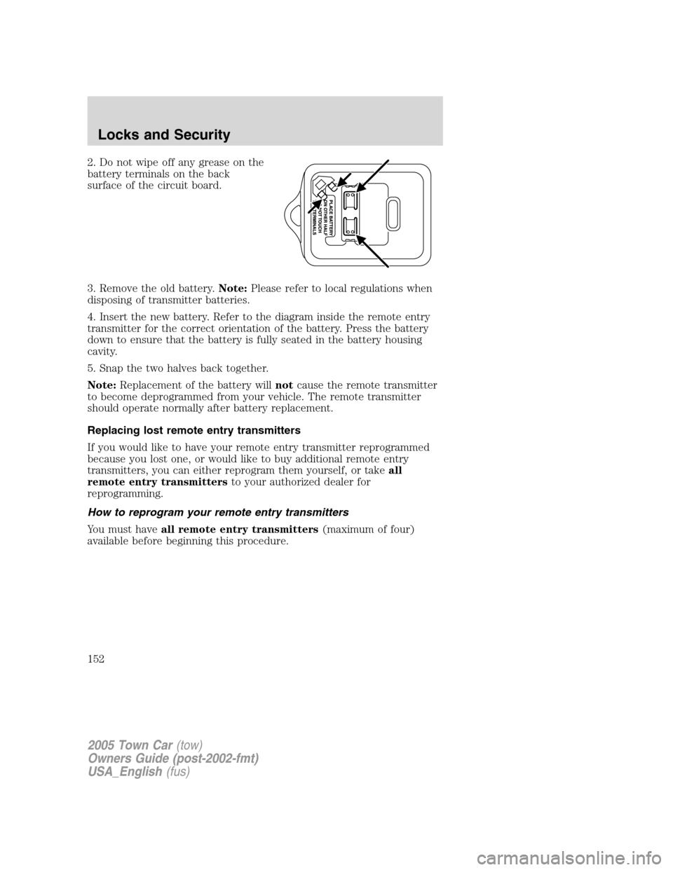
2. Do not wipe off any grease on the
battery terminals on the back
surface of the circuit board.
3. Remove the old battery.Note:Please refer to local regulations when
disposing of transmitter batteries.
4. Insert the new battery. Refer to the diagram inside the remote entry
transmitter for the correct orientation of the battery. Press the battery
down to ensure that the battery is fully seated in the battery housing
cavity.
5. Snap the two halves back together.
Note:Replacement of the battery willnotcause the remote transmitter
to become deprogrammed from your vehicle. The remote transmitter
should operate normally after battery replacement.
Replacing lost remote entry transmitters
If you would like to have your remote entry transmitter reprogrammed
because you lost one, or would like to buy additional remote entry
transmitters, you can either reprogram them yourself, or takeall
remote entry transmittersto your authorized dealer for
reprogramming.
How to reprogram your remote entry transmitters
You must haveall remote entry transmitters(maximum of four)
available before beginning this procedure.
2005 Town Car(tow)
Owners Guide (post-2002-fmt)
USA_English(fus)
Locks and Security
152
Page 154 of 328
•any door is open.
The battery saver will shut off the interior lamps 30 minutes after the
last door is closed, or after 10 minutes if the last door is left open.
Autolock
This feature automatically locks all vehicle doors when the following
conditions are met:
•all the doors are closed,
•the engine is running,
•you shift into gear, putting the vehicle in motion, and.
•the vehicle’s speed is greater than 3 mph (5 km/h).
Relock
The autolock feature repeats when the following conditions are met:
•any door is opened then closed while the engine is running, and
•you shift into gear, putting the vehicle in motion, and.
•the vehicle’s speed is greater than 3 mph (5 km/h).
To deactivate/reactivate the autolock feature using the power door
unlock control
You must complete Steps 1-7 within 30 seconds or the procedure will
have to be repeated. If the procedure needs to be repeated, you must
wait 30 seconds.
1. Turn the ignition to the 3 (ON) position.
2. Press the power door unlock control three times.
3. Turn the ignition from the 3 (ON) to the 1 (OFF/LOCK) position.
4. Press the power door unlock control three times.
5. Turn the ignition back to the 3 (ON) position. The door locks will
cycle to lock and unlock.
6. Press the unlock control. After five seconds, the horn will chirp once
to indicate the enabling/disabling of the autolock feature.
7. Turn the ignition to thye 1 (OFF/LOCK) position.
Memory seat/mirrors/adjustable pedals feature (if equipped)
The remote keyless entry system can also control the memory
seats/mirrors/adjustable pedals feature. With this feature, the first two
programmed transmitters will recall a different memory position.
2005 Town Car(tow)
Owners Guide (post-2002-fmt)
USA_English(fus)
Locks and Security
154
Page 251 of 328
GETTING ROADSIDE ASSISTANCE
To fully assist you should you have a vehicle concern, Ford Motor
Company offers a complimentary roadside assistance program. This
program is separate from the New Vehicle Limited Warranty. The service
is available:
•24–hours, seven days a week
•for the New Vehicle Limited Warranty period of three years or 36,000
miles (60,000 km), whichever occurs first on Ford and Mercury
vehicles, and four years or 50,000 miles (80,000 km) on Lincoln
vehicles.
Roadside assistance will cover:
•a flat tire change with a good spare (except Ford GT which has a tire
inflation kit)
•battery jump start
•lock-out assistance (key replacement cost is the customer’s
responsibility)
•fuel delivery (2.0 gallons [7.5L], maximum two occurrences within 12
month period)
•towing of your disabled vehicle to the nearest Ford Motor Company
dealership, or your selling dealer if within 35 miles (56.3 km) of the
nearest Ford Motor Company dealership (one tow per disablement).
Even non-warranty related tows, like accidents, are covered (some
exclusions apply, such as impound towing or repossession).
Canadian customers refer to your Owner Information Guide for
information on:
•coverage period
•exact fuel amounts
•towing of your disabled vehicle
•emergency travel expense reimbursement
•travel planning benefits
USING ROADSIDE ASSISTANCE
Complete the roadside assistance identification card and place it in your
wallet for quick reference. In the United States, this card is found in the
Owner Guide portfolio in the glove compartment. In Canada, the card is
found in theOwner Information Guidein the glove compartment.
U.S. Ford or Mercury vehicle customers who require roadside assistance,
call 1–800–241–3673; Lincoln vehicle customers call 1–800–521–4140.
2005 Town Car(tow)
Owners Guide (post-2002-fmt)
USA_English(fus)
Roadside Emergencies
251
Page 252 of 328
Canadian customers who require roadside assistance, call
1–800–665–2006.
If you need to arrange roadside assistance for yourself, Ford Motor
Company will reimburse a reasonable amount. To obtain reimbursement
information, U.S. Ford or Mercury vehicles customers call
1-800-241-3673; Lincoln vehicle customers call 1–800–521–4140.
Canadian customers who need to obtain reimbursement information, call
1–800–665–2006.
ROADSIDE COVERAGE BEYOND BASIC WARRANTY
In the United States, you may purchase additional roadside assistance
coverage beyond this period through the Ford Auto Club by contacting
your Ford or Lincoln Mercury dealer.
Similarly in Canada, for uninterrupted Roadside Assistance coverage, you
may purchase extended coverage prior to your Basic Warranty’s Roadside
Assistance expiring. For more information and enrollment, contact
1–877–294–2582 or visit our website at www.ford.ca.
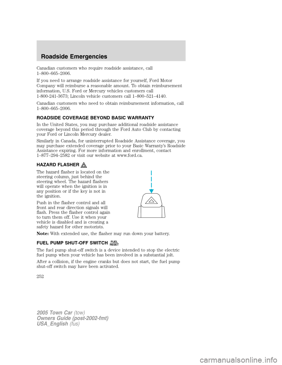
HAZARD FLASHER
The hazard flasher is located on the
steering column, just behind the
steering wheel. The hazard flashers
will operate when the ignition is in
any position or if the key is not in
the ignition.
Push in the flasher control and all
front and rear direction signals will
flash. Press the flasher control again
to turn them off. Use it when your
vehicle is disabled and is creating a
safety hazard for other motorists.
Note:With extended use, the flasher may run down your battery.
FUEL PUMP SHUT-OFF SWITCH
FUEL
RESET
The fuel pump shut-off switch is a device intended to stop the electric
fuel pump when your vehicle has been involved in a substantial jolt.
After a collision, if the engine cranks but does not start, the fuel pump
shut-off switch may have been activated.
2005 Town Car(tow)
Owners Guide (post-2002-fmt)
USA_English(fus)
Roadside Emergencies
252
Page 257 of 328
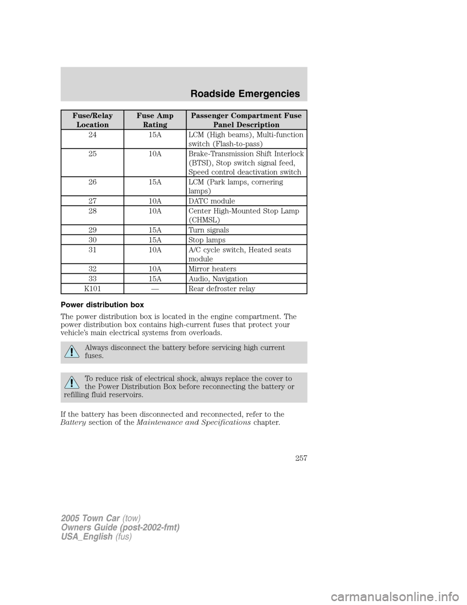
Fuse/Relay
LocationFuse Amp
RatingPassenger Compartment Fuse
Panel Description
24 15A LCM (High beams), Multi-function
switch (Flash-to-pass)
25 10A Brake-Transmission Shift Interlock
(BTSI), Stop switch signal feed,
Speed control deactivation switch
26 15A LCM (Park lamps, cornering
lamps)
27 10A DATC module
28 10A Center High-Mounted Stop Lamp
(CHMSL)
29 15A Turn signals
30 15A Stop lamps
31 10A A/C cycle switch, Heated seats
module
32 10A Mirror heaters
33 15A Audio, Navigation
K101 — Rear defroster relay
Power distribution box
The power distribution box is located in the engine compartment. The
power distribution box contains high-current fuses that protect your
vehicle’s main electrical systems from overloads.
Always disconnect the battery before servicing high current
fuses.
To reduce risk of electrical shock, always replace the cover to
the Power Distribution Box before reconnecting the battery or
refilling fluid reservoirs.
If the battery has been disconnected and reconnected, refer to the
Batterysection of theMaintenance and Specificationschapter.
2005 Town Car(tow)
Owners Guide (post-2002-fmt)
USA_English(fus)
Roadside Emergencies
257
Page 260 of 328
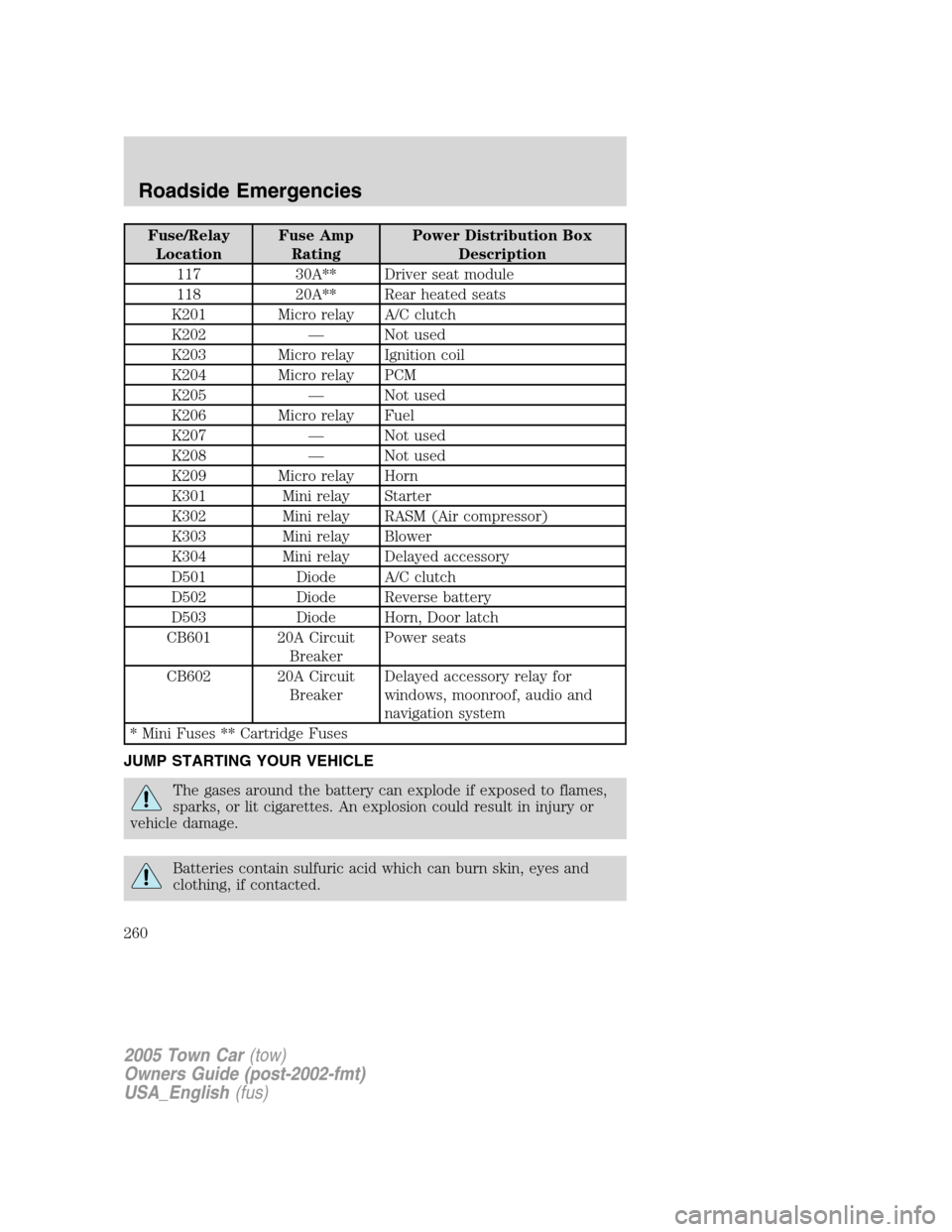
Fuse/Relay
LocationFuse Amp
RatingPower Distribution Box
Description
117 30A** Driver seat module
118 20A** Rear heated seats
K201 Micro relay A/C clutch
K202 — Not used
K203 Micro relay Ignition coil
K204 Micro relay PCM
K205 — Not used
K206 Micro relay Fuel
K207 — Not used
K208 — Not used
K209 Micro relay Horn
K301 Mini relay Starter
K302 Mini relay RASM (Air compressor)
K303 Mini relay Blower
K304 Mini relay Delayed accessory
D501 Diode A/C clutch
D502 Diode Reverse battery
D503 Diode Horn, Door latch
CB601 20A Circuit
BreakerPower seats
CB602 20A Circuit
BreakerDelayed accessory relay for
windows, moonroof, audio and
navigation system
* Mini Fuses ** Cartridge Fuses
JUMP STARTING YOUR VEHICLE
The gases around the battery can explode if exposed to flames,
sparks, or lit cigarettes. An explosion could result in injury or
vehicle damage.
Batteries contain sulfuric acid which can burn skin, eyes and
clothing, if contacted.
2005 Town Car(tow)
Owners Guide (post-2002-fmt)
USA_English(fus)
Roadside Emergencies
260
Page 261 of 328
Do not attempt to push-start your vehicle. Automatic
transmissions do not have push-start capability; doing so may
damage the catalytic converter.
Preparing your vehicle
When the battery is disconnected or a new battery is installed, the
transmission must relearn its shift strategy. As a result, the transmission
may have firm and/or soft shifts. This operation is considered normal and
will not affect function or durability of the transmission. Over time, the
adaptive learning process will fully update transmission operation.
1.Use only a 12–volt supply to start your vehicle.
2. Do not disconnect the battery of the disabled vehicle as this could
damage the vehicle’s electrical system.
3. Park the booster vehicle close to the hood of the disabled vehicle
making sure the two vehiclesdo nottouch. Set the parking brake on
both vehicles and stay clear of the engine cooling fan and other moving
parts.
4. Check all battery terminals and remove any excessive corrosion before
you attach the battery cables. Ensure that vent caps are tight and level.
5. Turn the heater fan on in both vehicles to protect any electrical
surges. Turn all other accessories off.
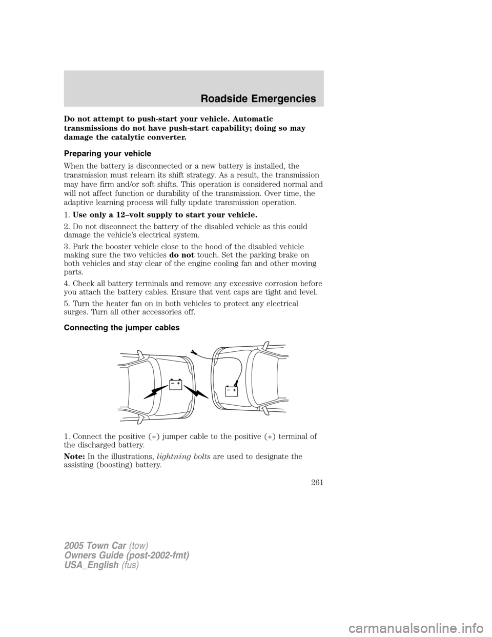
Connecting the jumper cables
1. Connect the positive (+) jumper cable to the positive (+) terminal of
the discharged battery.
Note:In the illustrations,lightning boltsare used to designate the
assisting (boosting) battery.
+–+–
2005 Town Car(tow)
Owners Guide (post-2002-fmt)
USA_English(fus)
Roadside Emergencies
261
Page 262 of 328
2. Connect the other end of the positive (+) cable to the positive (+)
terminal of the assisting battery.
3. Connect the negative (-) cable to the negative (-) terminal of the
assisting battery.
+–+–
+–+–
2005 Town Car(tow)
Owners Guide (post-2002-fmt)
USA_English(fus)
Roadside Emergencies
262