Page 526 of 969

8 mm (0.31 in.)
A78783
LH Cylinder:
10 mm (0.39 in.)
8 mm (0.31 in.) 14-150
- ENGINE MECHANICALCYLINDER HEAD ASSY (3MZ-FE)
2242 Author�: Date�:
2005")
A05239
A05240
A78782
RH Cylinder:
10 mm (0.39 in.)
8 mm (0.31 in.)
A78783
LH Cylinder:
10 mm (0.39 in.)
8 mm (0.31 in.) 14-150
- ENGINE MECHANICALCYLINDER HEAD ASSY (3MZ-FE)
2242 Author�: Date�:
2005 LEXUS ES330 REPAIR MANUAL (RM1124U)
(d) Lay a strip of Plastigage across each of the camshaft jour-
nals.
(e) Install the bearing caps.
Torque: 16 NVm (163 kgfVcm, 12 ftVlbf)
NOTICE:
Do not turn the camshaft.
(f) Remove the bearing caps.
(g) Measure the Plastigage at its widest point.
Standard oil clearance:
Intake #4, #5 journals
0.025 to 0.057 mm (0.0010 to 0.0022 in.)
Other journals 0.025 to 0.062 mm (0.0010 to 0.0024 in.)
Maximum oil clearance 0.10 mm (0.0039 in.)
�If the oil clearance is greater than maximum, re-
place the camshaft.
�If necessary, replace the bearing caps and cylinder
head together.
NOTICE:
Completely remove the Plastigage.
24. INSTALL RING W/HEAD PIN (RH CYLINDER)
(a) Using a plastic-faced hammer, tap in a new ring pin to the
specified protrusion height.
Protrusion height: 3 mm (0.12 in.)
25. INSTALL RING PIN (LH CYLINDER)
(a) Using a plastic-faced hammer, tap in a new ring pin to the
specified protrusion height.
Protrusion height: 3 mm (0.12 in.)
Page 527 of 969

14-151
2243 Author�: Date�:
2005 LEXUS ES330 REPAIR")
A78784
Protrusion Height
Mark
A78785
Wooden
BlockPress
Protrusion
Height
A78786
Wooden
Block
Flush
- ENGINE MECHANICALCYLINDER HEAD ASSY (3MZ-FE)
14-151
2243 Author�: Date�:
2005 LEXUS ES330 REPAIR MANUAL (RM1124U)
26. INSTALL SPARK PLUG TUBE
(a) Using paint, mark the standard height from the edge.
Standard protrusion height:
42.4 to 43.4 mm (1.669 to 1.709 in.)
HINT:
Use either end of the spark plug tube.
(b) Apply adhesive to the end of the spark plug tube which will
be pressed into the cylinder head.
Adhesive: Part No. 08833-00070 THREE BOND 1324
or equivalent
NOTICE:
�Install the spark plug tube within 3 minutes after ap-
plying adhesive.
�Do not deform the spark plug tube.
�Do not expose the spark plug tube to coolant within
1 hour after installing.
(c) Using a press and wooden block, install the spark plug
tube to the required protrusion height.
NOTICE:
Be careful not to drip the adhesive.
27. INSTALL PCV PIPE (RH CYLINDER)
(a) Using a wooden block and hammer, tap in 2 new PCV
pipes until their top edges are flush with the cylinder head
edge.
NOTICE:
Be careful not to damage the cylinder head edge.
Page 550 of 969
A78319
Front Side:
Upper Side:Right Side:
Lower Side:
Back Side: Back Side: Protrusion Height: 6 mm (0.24 in.)
Protrusion Height: 11 mm (0.43 in.) 4 mm
(0.16 in)
10 mm
(0.39 in.)
22 mm
(0.87 in.)12 mm
(0.47 in.) 12 mm
(0.47 in.)4 mm
(0.16 in)
4 mm
(0.16 in)
12 mm
(0.47 in.)4 mm
(0.16 in)
12 mm
(0.47 in.)
4 mm
(0.16 in)
12 mm
(0.47 in.) Protrusion Height: 6 mm (0.24 in.)
Protrusion Height: 6 mm (0.24 in.)Protrusion Height: 6 mm (0.24 in.) Protrusion Height: 6 mm (0.24 in.) 14-174
- ENGINE MECHANICALCYLINDER BLOCK ASSY (3MZ-FE)
2266 Author�: Date�:
2005 LEXUS ES330 REPAIR MANUAL (RM1124U)
32. INSTALL STRAIGHT PIN
Page 551 of 969
A78816
Upper Side:
Protrusion Height: 10 mm (0.39 in.) Protrusion Height: 4 mm (0.16 in.)16 mm
(0.63 in.)
20 mm
(0.79 in.)11 mm
(0.43 in.)
8 mm
(0.31 in.)
P12418A32958
A78817
80�C (176�F)
A78376
Front Mark
Front Mark
(Mold Mark)
- ENGINE MECHANICALCYLINDER BLOCK ASSY (3MZ-FE)
14-175
2267 Author�: Date�:
2005 LEXUS ES330 REPAIR MANUAL (RM1124U)
33. INSTALL RING PIN
34. INSTALL PISTON PIN HOLE SNAP RING
(a) Using a small screwdriver, install a new snap ring at one
end of the piston pin hole.
HINT:
Be sure that the end gap of the snap ring is not aligned with the
pin hole cutout of the piston.
35. INSTALL W/PIN PISTON SUB-ASSY
(a) Gradually heat the piston up to approximately 80�C
(176�F).
(b) Coat the piston pin with engine oil.
(c) Align the front marks of the piston and connecting rod,
then push in the piston pin with your thumb until the pin
contacts the snap ring.
Page 675 of 969
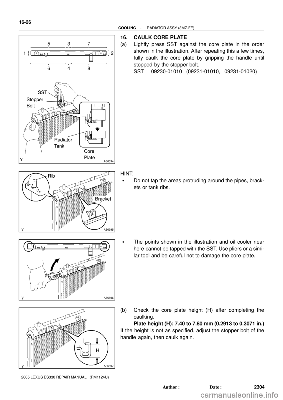
A86594
5
SST
Stopper
Bolt
Radiator
Tank
Core
Plate 1
6482 7 3
A86595
Rib
Bracket
A86596
A86597
H 16-26
- COOLINGRADIATOR ASSY (3MZ-FE)
2304 Author�: Date�:
2005 LEXUS ES330 REPAIR MANUAL (RM1124U)
16. CAULK CORE PLATE
(a) Lightly press SST against the core plate in the order
shown in the illustration. After repeating this a few times,
fully caulk the core plate by gripping the handle until
stopped by the stopper bolt.
SST 09230-01010 (09231-01010, 09231-01020)
HINT:
�Do not tap the areas protruding around the pipes, brack-
ets or tank ribs.
�The points shown in the illustration and oil cooler near
here cannot be tapped with the SST. Use pliers or a simi-
lar tool and be careful not to damage the core plate.
(b) Check the core plate height (H) after completing the
caulking.
Plate height (H): 7.40 to 7.80 mm (0.2913 to 0.3071 in.)
If the height is not as specified, adjust the stopper bolt of the
handle again, then caulk again.
Page 705 of 969
.
Does the ve")
2606R-02
START
Preliminary Check
��Tire pressure
��Vehicle height
��Brake dragging ROAD TEST
Does the vehicle lead/pull?
Cross switch front tire & wheel
assemblies (left & right).
Does the vehicle lead/pull in
same direction as before?
Check front wheel alignment.
Is it within specification?
Adjust front wheel alignment.Reverse the front left side
tire and rebalance it.
Does the vehicle
lead/pull to the left?
COMPLETE
Are the tires uni-directional type?
Choose the position of front tire & wheel
assemblies where there is least amount of pull.
Increase left front camber and decrease
right front camber until lead/pull is eliminated.Increase right front camber and decrease
left front camber until lead/pull is eliminated.
NO
YES
YES
NO
YES
YES
NO
YES
NO COMPLETE
NONOYES NOIs there steering
off center?
Adjust front tie rods.
NO
YES
Is the lead/pull stronger
than before?
YES
NOTICE : Do not exceed 1° of cross camber.
Do not exceed adjustment range.
Select a flat road where the vehicle can be driven in a straight line for 100 meters at a constant speed
of 35mph. Please confirm safety and set the steering wheel to its straight position. Drive the vehicle in
a straight line for 100 meters at a constant speed of 35mph without holding the steering wheel.
(1) The vehicle can keep straight but the steering wheel has some angle.
STEERING OFF CENTER (See page 50-4)
(2) The vehicle cannot keep straight.
STEERING PULL
YES NO
YES ROAD TEST
Does the vehicle still lead/pull?
NO ROAD TEST
Does the vehicle still lead/pull? ROAD TEST
Does the vehicle still lead/pull?
ROAD TEST
Does the vehicle still lead/pull?NO
Contact your local retail tire distributor.YES
*
*
26-2
- FRONT SUSPENSIONFRONT SUSPENSION SYSTEM
2365 Author�: Date�:
2005 LEXUS ES330 REPAIR MANUAL (RM1124U)
REPAIR
HINT:
This is the repair procedure for vehicle pull.
Page 708 of 969

26-5
2368 Author�: Date�:
2005 LEXUS ES330 REPAIR MANUAL (RM1124U)
FRO")
2605T-05
C91608
B Front:A
C91609
C Rear:
D
SA3213
A
DB
Front
C
F40165
- FRONT SUSPENSIONFRONT WHEEL ALIGNMENT (From July, 2003)
26-5
2368 Author�: Date�:
2005 LEXUS ES330 REPAIR MANUAL (RM1124U)
FRONT WHEEL ALIGNMENT (From July, 2003)
ADJUSTMENT
1. INSPECT TIRE (See page 26-5)
2. MEASURE VEHICLE HEIGHT
Vehicle height:
FrontA - B: 120 mm (4.72 in.)
RearD - C: 52 mm (2.05 in.)
Measuring points:
A: Ground clearance of front wheel center
B: Ground clearance of lower suspension arm No. 2 set bolt
center
C: Ground clearance of strut rod set bolt center
D: Ground clearance of rear wheel center
NOTICE:
Before inspecting the wheel alignment, adjust the vehicle
height to the specified value.
HINT:
Bounce the vehicle at the corners up and down to stabilize the
suspension and inspect the vehicle height.
3. INSPECT TOE-IN
Toe-in:
Toe-in
(total)A + B: 0° ± 12' (0° ± 0.2°)
C - D: 0 ± 2 mm (0 ± 0.08 in.)
If the toe-in is not within the specified value, adjust it at the rack
ends.
4. ADJUST TOE-IN
(a) Remove the rack boot set clips.
(b) Loosen the tie rod end lock nuts.
(c) Turn the right and left rack ends by an equal amount to
adjust the toe-in.
HINT:
Try to adjust the toe-in to the center of the specified value.
(d) Make sure that the lengths of the right and left rack ends
are the same.
(e) Torque the tie rod end lock nuts.
Torque: 74 N´m (755 kgf´cm, 55 ft´lbf)
(f) Place the boots on the seats and install the clips.
HINT:
Make sure that the boots are not twisted.
(g) Perform VSC system calibration. (See page 05-471)
Page 734 of 969

N00372
HeightThickness
Length
R10282
Feeler Gauge
F41490
F41491F41622
Compressed Air
R08702
Vernier Calipers
51-12
- POWER STEERINGVANE PUMP ASSY
2587 Author�: Date�:
2005 LEXUS ES330 REPAIR MANUAL (RM1124U)
26. INSPECT VANE PUMP ROTOR AND VANE PUMP
PLATES
(a) Using a micrometer, measure the height, thickness and
length of the vane pump plates.
Minimum height: 8.6 mm (0.339 in.)
Minimum thickness: 1.397 mm (0.05500 in.)
Minimum length: 14.991 mm (0.59020 in.)
(b) Using a feeler gauge, measure the clearance between
the vane pump rotor groove and vane pump plate.
Maximum clearance: 0.03 mm (0.0012 in.)
If it is more than the maximum, replace the vane pump assy.
27. INSPECT FLOW CONTROL VALVE
(a) Coat the flow control valve with power steering fluid and
check that it falls smoothly into the flow control valve hole
by its own weight.
(b) Check the flow control valve for leakage. Close one of the
holes and apply compressed air of 392 - 490 kPa (4 - 5
kgf/cm
2, 57 - 71 psi) into the opposite side hole, and con-
firm that air does not come out from the end holes.
If necessary, replace the vane pump assy.
28. INSPECT FLOW CONTROL VALVE COMPRESSION
SPRING
(a) Using vernier calipers, measure the free length of the flow
control valve compression spring.
Minimum free length: 32.24 mm (1.2693 in.)
If it is not within the specification, replace the vane pump assy.

Protrusion Height: 11 mm (0.43 in.) 4 mm
(0.16 in)
10 mm
(0.39 in.)
22 mm
(0.87 in.)12")