Page 270 of 424
CAUTION!
After inspecting or adjusting the tire pressure al-
ways reinstall the valve stem cap. This will prevent
moisture and dirt from entering the valve stem,
which could damage the wheel rim sensor.
NOTE:
•The TPM system can inform the driver of a low tire
pressure condition.
•The TPM system is not intended to replace normal tire
care and maintenance, nor to provide warning of a tire
failure or condition.
•The TPM system should not be used as a tire pressure
gauge while adjusting your tire pressure.
Tire Pressure Monitoring — Premium System
The Tire Pressure Monitor System (TPM) system uses
wireless technology with wheel rim mounted electronic
sensors to monitor tire pressure levels. Sensors mounted
to each wheel as part of the valve stem transmit tire
pressure readings to the Receiver Module. The wheel
sensors monitor tire pressure, and status for all four
active road tires and the spare tire. The spare tire pressure
is monitored, but not displayed.
NOTE:It is particularly important, for you to check the
tire pressure in all of your tires regularly and to maintain
the proper pressure.
The Tire Pressure Monitoring Indicator Lamp will
illuminate in the instrument cluster, and an au-
dible chime will be activated when one or more
tire pressures is low. The Tire Pressure Monitoring Indi-
cator Lamp will flash on and off for ten seconds when a
270 STARTING AND OPERATING
Page 271 of 424
system fault is detected. The flash cycle will repeat every
ten minutes or until the fault condition is removed and
reset.
The Tire Pressure Monitoring System consists of the
following components:
•Receiver Module
•4/5 Wheel Sensors
•4 Wheel Sensor Trigger Modules
•Tire Pressure Monitoring System Display Messages in
the EVIC
•Amber Colored Tire Pressure Monitoring Indicator
Lamp
The system consists of tire pressure monitoring sensors
attached to each wheel through the valve stem mounting
hole, a central receiver module, Wheel Sensor Trigger
Modules mounted in three of the four wheel wells,various Tire Pressure Monitoring System Display Mes-
sages in the EVIC, and an amber colored Indicator Lamp.
A sensor shall be installed in the spare wheel if the
vehicle is equipped with a matching full size spare wheel
and tire assembly.
NOTE:For vehicles with optional wheel/tire sizes and
significantly different tire placard pressures, the placard
pressure value and the low-pressure threshold value is
re-programmable at your authorized dealer to accommo-
date the customer selected wheel/tire combinations rec-
ommended by DaimlerChrysler.
The following�warnings�will cause a text message to be
displayed, an audible chime to sound and the tire pres-
sure Indicator Lamp to illuminate. The audible chime
will occur once every ignition cycle for each�warning�
detected. The tire pressure Indicator Lamp will illumi-
nate continuously (solid) and shall remain illuminated
until the warning condition is removed/reset.
STARTING AND OPERATING 271
5
Page 272 of 424
NOTE:The Indicator Lamp will only illuminate for the
four active road tires. A low spare tire pressure will not
cause the Indicator Lamp to illuminate
When the appropriate conditions exist, the Electronic
Vehicle Information Center (EVIC) displays the following
messages.
LEFT FRONT, LEFT REAR, RIGHT FRONT,
RIGHT REAR LOW PRESSURE, SPARE LOW
PRESSURE
One or more of these messages will be displayed in the
EVIC if a low tire pressure condition exists in one or more
tires.
Inspect all tires for proper inflation pressure, once the
proper tire pressure has been set, the TPM system
warning will reset automatically when the vehicle has
been driven for at least 2 minutes at or above 15 mph (24
km/h).
CHECK TPM SYSTEM
See your authorized dealer when this message appears in
the EVIC. This message indicates that a system fault
condition has been detected.
CAUTION!
The TPM system has been optimized for the original
equipment tires and wheels. TPM system pressures
have been established for the tire size equipped on
your vehicle. Undesirable system operation or sen-
sor damage may result when using replacement
equipment that is not of the same size, type, and/or
style. After-market wheels can cause sensor damage.
Do not use tire sealant from a can, or balance beads
if your vehicle is equipped with a TPM system, as
damage to the sensors may result.
272 STARTING AND OPERATING
Page 291 of 424
WHAT TO DO IN EMERGENCIES
CONTENTS
�Hazard Warning Flashers.................292
�If Your Engine Overheats.................293
�Jacking And Tire Changing................294
▫Jack Location........................295
▫Spare Tire Stowage....................295
▫Preparations For Jacking................296▫Jacking Instructions....................296
�Jump Starting Procedure..................299
�Emergency Tow Hooks — If Equipped........301
�Towing A Disabled Vehicle................302
▫2WD Models Only....................302
▫4WD Models Only....................302
6
Page 295 of 424
Jack Location
The scissor-type jack, and tire changing tools are stored
beneath the right rear seat. To remove the jack from its
stowage position, turn the thumb screw counterclock-
wise to loosen jack assembly and then remove it.
Spare Tire Stowage
To remove the spare tire from the carrier, remove the tire
cover, if equipped, and remove the lug nuts with the lug
wrench turning them counterclockwise.
Jack Storage Location
Spare Tire Mounting
WHAT TO DO IN EMERGENCIES 295
6
Page 296 of 424
NOTE:If you have added aftermarket accessories to the
spare tire mounted carrier, it cannot exceed a gross
weight of 50 lbs (23 kg) including the weight of the spare
tire.
Preparations For Jacking
Park the vehicle on a firm level surface, avoid ice or
slippery areas,set the parking brakeand place auto-
matic transmission in P (Park), or manual transmission in
R (Reverse). Turn OFF the ignition.
WARNING!
Do not attempt to change a tire on the side of the
vehicle close to moving traffic. Pull far enough off
the road to avoid being hit when operating the jack
or changing the wheel.
•Turn on the Hazard Warning Flasher.
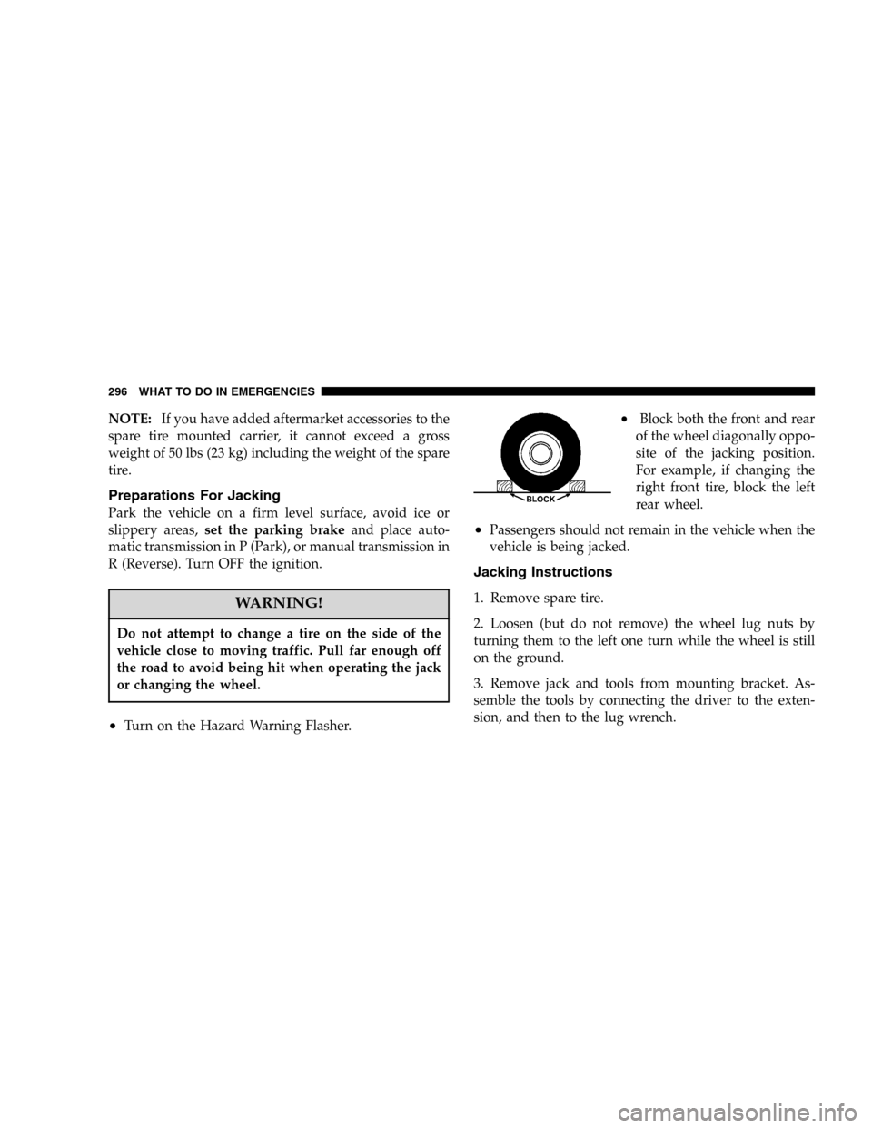
•Block both the front and rear
of the wheel diagonally oppo-
site of the jacking position.
For example, if changing the
right front tire, block the left
rear wheel.
•Passengers should not remain in the vehicle when the
vehicle is being jacked.
Jacking Instructions
1. Remove spare tire.
2. Loosen (but do not remove) the wheel lug nuts by
turning them to the left one turn while the wheel is still
on the ground.
3. Remove jack and tools from mounting bracket. As-
semble the tools by connecting the driver to the exten-
sion, and then to the lug wrench.
296 WHAT TO DO IN EMERGENCIES
Page 297 of 424
4. Locate the jack as shown. For the front tires, place it in
the notch on the body weld seam behind wheel to be
changed. For the rear tires, place it under the axle by the
wheel to be changed. Position the jack handle on the jack.
Do not raise the vehicle until you are sure the jack is
fully engaged.
5. Raise the vehicle by turning the jack screw to the right.
Raise the vehicle only until the tire just clears the surface
and enough clearance is obtained to install the spare tire.
Minimum tire lift provides maximum stability.
Front Jacking Location
Rear Jacking Location
WHAT TO DO IN EMERGENCIES 297
6
Page 298 of 424
WARNING!
Raising the vehicle higher than necessary can make
the vehicle less stable and cause an accident. It could
slip off the jack and hurt someone near it. Raise the
vehicle only enough to remove the tire.
6. Remove the lug nuts and wheel.
7. Position the spare wheel/tire on the vehicle and install
lug nuts with cone-shaped end toward wheel. Lightly
tighten the nuts. To avoid the risk of forcing the vehicle
off the jack, do not tighten the nuts fully until the vehicle
has been lowered.
8. Lower the vehicle by turning the jack screw to the left,
and remove the jack and wheel blocks.
9. Finish tightening the lug nuts. Push down on the
wrench while tightening for increased leverage. Alternatenuts until each nut has been tightened twice. Correct
wheel nut tightness is 130 N·m (95 ft. lbs). If in doubt
about the correct tightness, have them checked with a
torque wrench by your authorized dealer or at a service
station.
10. Lower the jack to it’s fully closed position.WARNING!
A loose tire or jack, thrown forward in a collision or
hard stop could endanger the occupants of the ve-
hicle. Always stow the jack parts and the spare tire in
the places provided.
11. Secure the tire, jack, and tools in their proper loca-
tions.
298 WHAT TO DO IN EMERGENCIES