Page 2913 of 3419
RSU-38
FRONT LOWER LINK
Revision: October 20052005 QX56
INSTALLATION
Installation is in the reverse order of removal.
�Tighten the nuts and bolts to specification. Refer to RSU-25, "Components" .
�Perform the final tightening of the nuts and bolts for the links (rubber bushing) under unladen condition
(unladen condition means that the fuel tank, engine coolant and lubricants are at the full specification, and
the spare tire, jack, hand tools, and mats are in their designated positions) with the tires on level ground.
�Check the wheel alignment. Refer to RSU-27, "Wheel Alignment Inspection" .
Page 2920 of 3419
HEIGHT SENSOR
RSU-45
C
D
F
G
H
I
J
K
L
MA
B
RSU
Revision: October 20052005 QX56
INSTALLATION
Installation is in the reverse order of removal.
1. Start the engine.
2. Use CONSULT-II to perform "STANDARD HEIGHT LEVEL" work support function.
3. Using data monitor of CONSULT-II, verify "HEIGT CALC" is at 0 mm.
4. Check the vehicle height. Refer to RSU-48, "
Wheelarch Height (Unladen*1 )" . If vehicle height is not
within ± 10 mm (0 ± 0.39 in) of the specification, perform the initialization procedure. Refer to RSU-46,
"Initialization Procedure" .
Page 2941 of 3419
SC-4
BATTERY
Revision: October 20052005 QX56
BATTERYPFP:AYBGL
How to Handle BatteryEKS00B78
CAUTION:
�If it becomes necessary to start the engine with a booster battery and jumper cables, use a 12-volt
booster battery.
�After connecting battery cables, ensure that they are tightly clamped to battery terminals for good
contact.
�Never add distilled water through the hole used to check specific gravity.
METHODS OF PREVENTING OVER-DISCHARGE
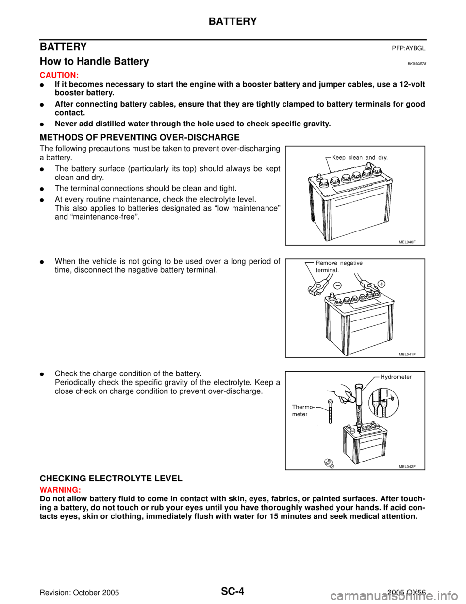
The following precautions must be taken to prevent over-discharging
a battery.
�The battery surface (particularly its top) should always be kept
clean and dry.
�The terminal connections should be clean and tight.
�At every routine maintenance, check the electrolyte level.
This also applies to batteries designated as “low maintenance”
and “maintenance-free”.
�When the vehicle is not going to be used over a long period of
time, disconnect the negative battery terminal.
�Check the charge condition of the battery.
Periodically check the specific gravity of the electrolyte. Keep a
close check on charge condition to prevent over-discharge.
CHECKING ELECTROLYTE LEVEL
WAR NIN G:
Do not allow battery fluid to come in contact with skin, eyes, fabrics, or painted surfaces. After touch-
ing a battery, do not touch or rub your eyes until you have thoroughly washed your hands. If acid con-
tacts eyes, skin or clothing, immediately flush with water for 15 minutes and seek medical attention.
MEL040F
MEL041F
MEL042F
Page 2951 of 3419
SC-14
STARTING SYSTEM
Revision: October 20052005 QX56
DIAGNOSTIC PROCEDURE 1
Check Starter Motor Circuit
1. CHECK POWER SUPPLY TO STARTER MOTOR
1. Remove the fuel pump fuse.
2. Crank or start the engine (where possible) until the fuel pressure is released.
3. Turn the ignition switch OFF.
4. Check that the starter motor connector F27 connection is clean and tight.
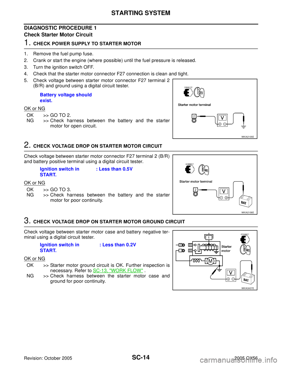
5. Check voltage between starter motor connector F27 terminal 2
(B/R) and ground using a digital circuit tester.
OK or NG
OK >> GO TO 2.
NG >> Check harness between the battery and the starter
motor for open circuit.
2. CHECK VOLTAGE DROP ON STARTER MOTOR CIRCUIT
Check voltage between starter motor connector F27 terminal 2 (B/R)
and battery positive terminal using a digital circuit tester.
OK or NG
OK >> GO TO 3.
NG >> Check harness between the battery and the starter
motor for poor continuity.
3. CHECK VOLTAGE DROP ON STARTER MOTOR GROUND CIRCUIT
Check voltage between starter motor case and battery negative ter-
minal using a digital circuit tester.
OK or NG
OK >> Starter motor ground circuit is OK. Further inspection is
necessary. Refer to SC-13, "
WORK FLOW" .
NG >> Check harness between the starter motor case and
ground for poor continuity. Battery voltage should
exist.
WKIA2105E
Ignition switch in
START.: Less than 0.5V
WKIA2106E
Ignition switch in
START.: Less than 0.2V
WKIA3437E
Page 2952 of 3419
STARTING SYSTEM
SC-15
C
D
E
F
G
H
I
J
L
MA
B
SC
Revision: October 20052005 QX56
DIAGNOSTIC PROCEDURE 2
Check Magnetic Switch Circuit
1. CHECK POWER SUPPLY FOR MAGNETIC SWITCH
1. Remove the fuel pump fuse.
2. Crank or start the engine (where possible) until the fuel pressure is released.
3. Turn the ignition switch OFF.
4. Disconnect starter motor connector F28.
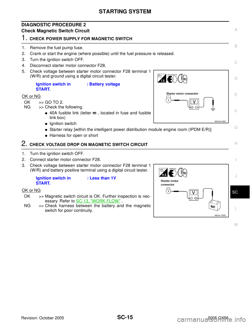
5. Check voltage between starter motor connector F28 terminal 1
(W/R) and ground using a digital circuit tester.
OK or NG
OK >> GO TO 2.
NG >> Check the following.
�40A fusible link (letter m , located in fuse and fusible
link box)
�Ignition switch
�Starter relay [within the intelligent power distribution module engine room (IPDM E/R)]
�Harness for open or short
2. CHECK VOLTAGE DROP ON MAGNETIC SWITCH CIRCUIT
1. Turn the ignition switch OFF.
2. Connect starter motor connector F28.
3. Check voltage between starter motor connector F28 terminal 1
(W/R) and battery positive terminal using a digital circuit tester.
OK or NG
OK >> Magnetic switch circuit is OK. Further inspection is nec-
essary. Refer to SC-13, "
WORK FLOW" .
NG >> Check harness between the battery and the magnetic
switch for poor continuity. Ignition switch in
START.: Battery voltage
WKIA2108E
Ignition switch in
START.: Less than 1V
WKIA1792E
Page 2956 of 3419
CHARGING SYSTEM
SC-19
C
D
E
F
G
H
I
J
L
MA
B
SC
Revision: October 20052005 QX56
Trouble Diagnoses with Battery/Starting/Charging System TesterEKS00B7J
NOTE:
To ensure a complete and thorough diagnosis, the battery, starter and generator test segments must be done
as a set from start to finish.
1. Turn off all loads on the vehicle electrical system.
2. Perform battery and starting system test with Battery/Starting/
Charging system tester.
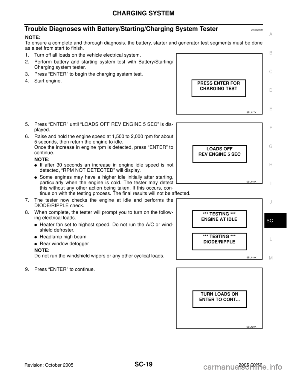
3. Press “ENTER” to begin the charging system test.
4. Start engine.
5. Press “ENTER” until “LOADS OFF REV ENGINE 5 SEC” is dis-
played.
6. Raise and hold the engine speed at 1,500 to 2,000 rpm for about
5 seconds, then return the engine to idle.
Once the increase in engine rpm is detected, press “ENTER” to
continue.
NOTE:
�If after 30 seconds an increase in engine idle speed is not
detected, “RPM NOT DETECTED” will display.
�Some engines may have a higher idle initially after starting,
particularly when the engine is cold. The tester may detect
this without any other action being taken. If this occurs, con-
tinue on with the testing process. The final results will not be affected.
7. The tester now checks the engine at idle and performs the
DIODE/RIPPLE check.
8. When complete, the tester will prompt you to turn on the follow-
ing electrical loads.
�Heater fan set to highest speed. Do not run the A/C or wind-
shield defroster.
�Headlamp high beam
�Rear window defogger
NOTE:
Do not run the windshield wipers or any other cyclical loads.
9. Press “ENTER” to continue.
SEL417X
SEL418X
SEL419X
SEL420X
Page 2960 of 3419
CHARGING SYSTEM
SC-23
C
D
E
F
G
H
I
J
L
MA
B
SC
Revision: October 20052005 QX56
DIAGNOSTIC PROCEDURE 2
Check Battery Circuit
1. CHECK BATTERY CIRCUIT CONNECTION
1. Turn the ignition switch OFF.
2. Check to see if terminal 1 is clean and tight.
OK or NG
OK >> GO TO 2.
NG >> Repair terminal 1 connection. Confirm repair by performing complete Battery/Starting/Charging
system test.
2. CHECK BATTERY CIRCUIT
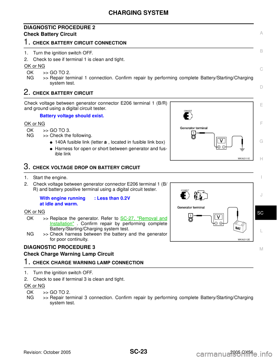
Check voltage between generator connector E206 terminal 1 (B/R)
and ground using a digital circuit tester.
OK or NG
OK >> GO TO 3.
NG >> Check the following.
�140A fusible link (letter a , located in fusible link box)
�Harness for open or short between generator and fus-
ible link
3. CHECK VOLTAGE DROP ON BATTERY CIRCUIT
1. Start the engine.
2. Check voltage between generator connector E206 terminal 1 (B/
R) and battery positive terminal using a digital circuit tester.
OK or NG
OK >> Replace the generator. Refer to SC-27, "Removal and
Installation" . Confirm repair by performing complete
Battery/Starting/Charging system test.
NG >> Check harness between the battery and the generator
for poor continuity.
DIAGNOSTIC PROCEDURE 3
Check Charge Warning Lamp Circuit
1. CHECK CHARGE WARNING LAMP CONNECTION
1. Turn the ignition switch OFF.
2. Check to see if terminal 3 is clean and tight.
OK or NG
OK >> GO TO 2.
NG >> Repair terminal 3 connection. Confirm repair by performing complete Battery/Starting/Charging
system test. Battery voltage should exist.
W K I A 2111 E
With engine running
at idle and warm.: Less than 0.2V
WKIA2112E
Page 2961 of 3419
SC-24
CHARGING SYSTEM
Revision: October 20052005 QX56
2. CHECK CHARGE WARNING LAMP CIRCUIT
1. Disconnect E205 connector from generator.
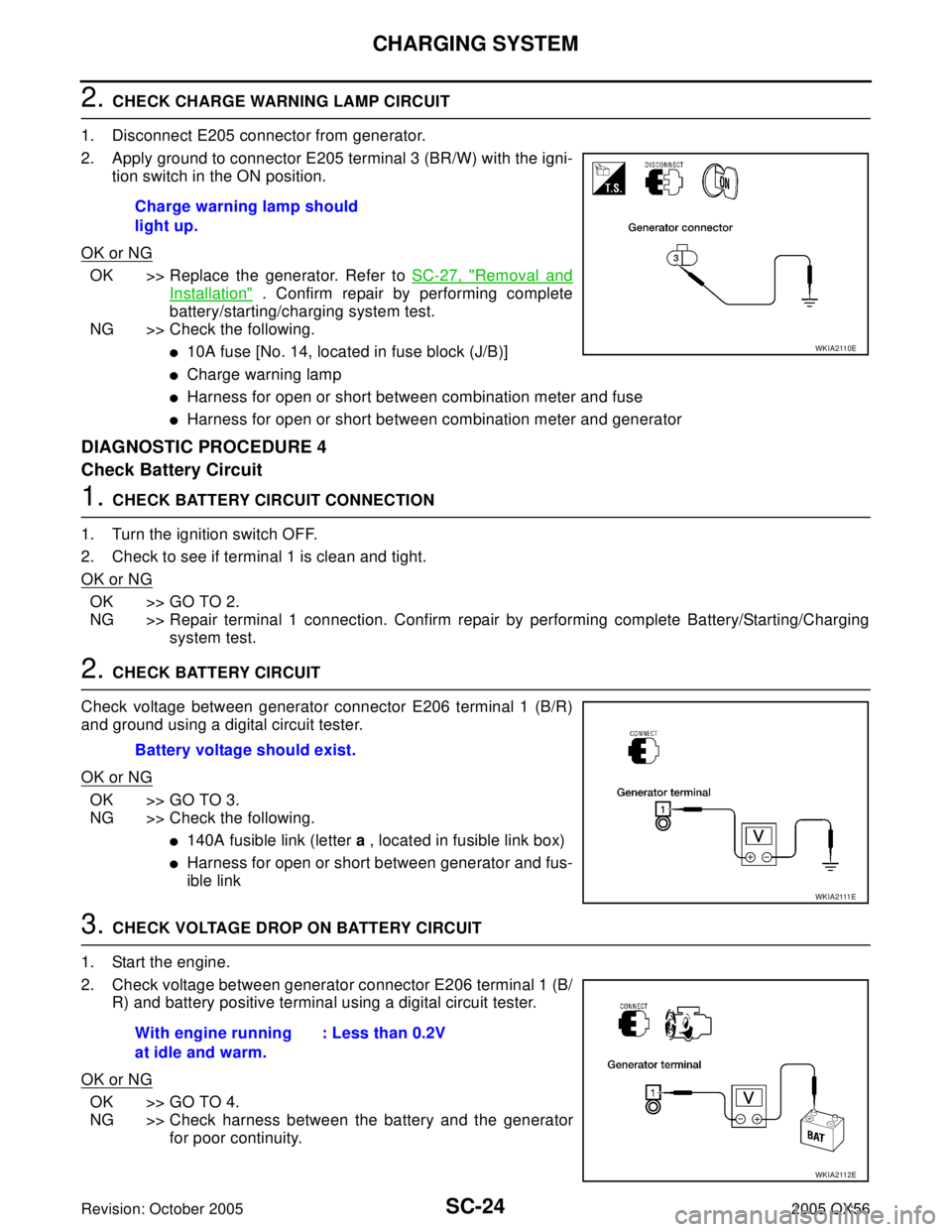
2. Apply ground to connector E205 terminal 3 (BR/W) with the igni-
tion switch in the ON position.
OK or NG
OK >> Replace the generator. Refer to SC-27, "Removal and
Installation" . Confirm repair by performing complete
battery/starting/charging system test.
NG >> Check the following.
�10A fuse [No. 14, located in fuse block (J/B)]
�Charge warning lamp
�Harness for open or short between combination meter and fuse
�Harness for open or short between combination meter and generator
DIAGNOSTIC PROCEDURE 4
Check Battery Circuit
1. CHECK BATTERY CIRCUIT CONNECTION
1. Turn the ignition switch OFF.
2. Check to see if terminal 1 is clean and tight.
OK or NG
OK >> GO TO 2.
NG >> Repair terminal 1 connection. Confirm repair by performing complete Battery/Starting/Charging
system test.
2. CHECK BATTERY CIRCUIT
Check voltage between generator connector E206 terminal 1 (B/R)
and ground using a digital circuit tester.
OK or NG
OK >> GO TO 3.
NG >> Check the following.
�140A fusible link (letter a , located in fusible link box)
�Harness for open or short between generator and fus-
ible link
3. CHECK VOLTAGE DROP ON BATTERY CIRCUIT
1. Start the engine.
2. Check voltage between generator connector E206 terminal 1 (B/
R) and battery positive terminal using a digital circuit tester.
OK or NG
OK >> GO TO 4.
NG >> Check harness between the battery and the generator
for poor continuity. Charge warning lamp should
light up.
WKIA2110E
Battery voltage should exist.
W K I A 2111 E
With engine running
at idle and warm.: Less than 0.2V
WKIA2112E