Page 1920 of 3419

INTAKE MANIFOLD
EM-17
C
D
E
F
G
H
I
J
K
L
MA
EM
Revision: October 20052005 QX56
INSTALLATION
Installation is in the reverse order of removal.
�Tighten the intake manifold bolts in numerical order as shown.
�Install the EVAP canister purge control solenoid valve connector with it facing front of engine.
�Tighten the electronic throttle control actuator bolts of the electric throttle control actuator equally and
diagonally in several steps.
�After installation perform procedure in EM-18, "INSPECTION AFTER INSTALLATION" .
�Install the water hose so that its overlap width for connection is between 27 mm (1.06 in) and 32 mm (1.26
in) (target: 27 mm 1.06 in).
Connecting Quick Connector of Fuel Tube
Install quick connector as follows (the steps are the same for quick connectors on both engine side and vehi-
cle side except for the quick connector cap).
1. Make sure no foreign substances are deposited in and around tube and quick connector, and they are not
damaged.
2. Thinly apply new engine oil around the fuel tube from tip end to the spool end.
3. Align center to insert quick connector straight into fuel tube.
�Insert until the paint mark for engagement identification
(white) goes completely inside quick connector so that you
cannot see it from the straight side of the connected part. Use
a mirror to check this where it is not possible to view directly
from the straight side, such as quick connector on vehicle
side.
�Insert fuel tube into quick connector until top spool is com-
pletely inside quick connector, and 2nd level spool exposes
right below quick connector on engine side.
CAUTION:
�Hold "A" position in illustration when inserting fuel
tube into quick connector.
�Carefully align center to avoid inclined insertion to pre-
vent damage to O-ring inside quick connector.
�Insert until you hear a “click” sound and actually feel
the engagement.
�To avoid misidentification of engagement with a similar
sound, be sure to perform the next step.
4. Pull quick connector by hand holding "A" position. Make sure it is completely engaged (connected) so that
it does not come out from fuel tube.
NOTE:
Recommended pulling force is 50 N (5.1 kg, 11.2 lb).
KBIA2462E
PBIC0017E
KBIA0272E
Page 1921 of 3419
EM-18Revision: October 2005
INTAKE MANIFOLD
2005 QX56
5. Install the quick connector cap on the quick connector joint (on
engine side only).
6. Install the fuel hose and tube to hose clamps.
7. Refill the engine coolant. Refer to MA-14, "
REFILLING ENGINE
COOLANT" .
INSPECTION AFTER INSTALLATION
�After installing fuel tubes, make sure there is no fuel leakage at connections in the following steps.
–Apply fuel pressure to fuel lines by turning ignition switch ON (with engine stopped). Then check for fuel
leaks at connections.
–Start the engine and rev it up and check for fuel leaks at the connections.
�Perform procedures for “Throttle Valve Closed Position Learning” after finishing repairs. Refer to EC-90,
"Throttle Valve Closed Position Learning" .
�If electric throttle control actuator is replaced, perform procedures for “Idle Air Volume Learning” after fin-
ishing repairs. Refer to EC-91, "
Idle Air Volume Learning" .
SBIA0354E
Page 1932 of 3419
FUEL INJECTOR AND FUEL TUBE
EM-29
C
D
E
F
G
H
I
J
K
L
MA
EM
Revision: October 20052005 QX56
FUEL INJECTOR AND FUEL TUBEPFP:16600
Removal and InstallationEBS00LM6
CAUTION:
Do not remove or disassemble parts unless instructed as shown in the figure.
REMOVAL
1. Remove the engine room cover using power tool. Refer to EM-11, "REMOVAL" .
2. Release the fuel pressure. Refer to EC-93, "
FUEL PRESSURE RELEASE" .
3. Disconnect the negative battery terminal.
4. Disconnect the fuel injector harness connectors.
5. Disconnect the fuel hose assembly from the fuel tubes (right bank and left bank).
CAUTION:
�While hoses are disconnected, plug them to prevent fuel from draining.
�Do not separate the fuel connector and fuel hose.
6. Remove the fuel injectors with the fuel tube assembly.
1. Fuel tube (right bank) 2. Cap 3. Fuel damper
4. O-ring 5. O-ring (blue) 6. Fuel injector
7. Clip 8. O-ring (brown) 9. O-ring
10. Fuel hose assembly 11. Fuel tube (left bank)
KBIA2472E
Page 1933 of 3419

EM-30Revision: October 2005
FUEL INJECTOR AND FUEL TUBE
2005 QX56
7. Remove the fuel injector from the fuel tube using the following
steps.
a. Spread open and remove the clip.
b. Remove the fuel injector from the fuel tube by pulling straight
out.
CAUTION:
�Be careful with remaining fuel that may leak out from fuel
tube.
�Do not damage injector nozzles during removal.
�Do not bump or drop fuel injectors.
�Do not disassemble fuel injectors.
8. Remove the fuel damper from each fuel tube.
INSTALLATION
1. Install the fuel damper to each fuel tube using the following
steps.
a. Apply engine oil to the new O-ring and set it into the cap of the
fuel tube.
CAUTION:
�Handle O-ring with bare hands. Never wear gloves.
�Lubricate O-ring with new engine oil.
�Do not clean O-ring with solvent.
�Make sure that O-ring and its mating part are free of for-
eign material.
�When installing O-ring, do not scratch it with tool or fin-
gernails.
�Do not twist or stretch the O-ring.
b. Make sure that the backup spacer is in the O-ring connecting surface of the fuel damper.
NOTE:
The backup spacer is part of the fuel damper assembly.
c. Insert the fuel damper until it seats on the fuel tube.
CAUTION:
�Insert straight, making sure that the axis is lined up.
�Do not pressure-fit with excessive force.
d. Install the cap, and then tighten the bolts evenly.
�After tightening the bolts, make sure that there is no gap between the cap and fuel tube.
2. Install new O-rings to the fuel injector paying attention to the items below.
CAUTION:
�Upper and lower O-ring are different.
KBIA2506E
Reference value :130 N (13.3 kg, 29.2 lb)
KBIA2473E
Page 1974 of 3419

ENGINE ASSEMBLY
EM-71
C
D
E
F
G
H
I
J
K
L
MA
EM
Revision: October 20052005 QX56
CAUTION:
�Be careful not to damage the drive plate. Especially
avoid deforming and damaging of the signal plate teeth
(circumference position).
�Place the drive plate with the signal plate surface fac-
ing other than downward.
�Keep magnetic materials away from the signal plate.
CAUTION:
Use an engine stand that has a load capacity [approximately 240kg (529 lb) or more] large enough
for supporting the engine weight.
�If the load capacity of the stand is not adequate, remove the following parts beforehand to
reduce the potential risk of overturning the stand.
–Remove the fuel tube and fuel injector assembly. Refer to EM-29, "REMOVAL" .
–Remove the intake manifold. Refer to EM-15, "REMOVAL" .
–Remove the ignition coil. Refer to EM-26, "REMOVAL" .
–Remove the rocker cover. Refer to EM-33, "REMOVAL" .
–Other removable brackets.
CAUTION:
Before removing the hanging chains, make sure the engine stand is stable and there is no risk of
overturning.
31. Remove the alternator. Refer to SC-27, "
REMOVAL" .
32. Remove the engine mounting insulator and bracket using power tool.
KBIA2491E
Page 2068 of 3419

FUEL SYSTEM
FL-3
C
D
E
F
G
H
I
J
K
L
MA
FL
Revision: October 20052005 QX56
FUEL SYSTEMPFP:17503
Checking Fuel LinesEBS00M3Q
Inspect fuel lines, fuel filler cap and fuel tank for improper attach-
ment, leaks, cracks, damage, loose connections, chafing or deterio-
ration.
If necessary, repair or replace damaged parts.
General PrecautionsEBS00M3R
WA RN ING:
When replacing fuel line parts, be sure to observe the following.
�Put a “CAUTION: INFLAMMABLE” sign in the workshop.
�Be sure to work in a well ventilated area and furnish workshop with a CO2 fire extinguisher.
�Do not smoke while servicing fuel system. Keep open flames and sparks away from the work area.
CAUTION:
�Before removing fuel line parts, carry out the following procedures:
–Put drained fuel in an explosion-proof container and put the lid on securely. Keep the container in
safe area.
–Release fuel pressure from the fuel lines. Refer to EC-93, "FUEL PRESSURE RELEASE" .
–Disconnect the battery negative terminal.
�Always replace O-rings and clamps with new ones.
�Do not kink or twist hoses when they are being installed.
�Do not tighten hose clamps excessively to avoid damaging
hoses.
Tighten high-pressure rubber hose clamp so that clamp
end is 3 mm (0.12 in) from hose end.
Tightening torque specifications are the same for all rubber
hose clamps.
Check that the screw does not contact adjacent parts.
SM A80 3A
MMA104A
Page 2069 of 3419
FL-4Revision: October 2005
FUEL SYSTEM
2005 QX56
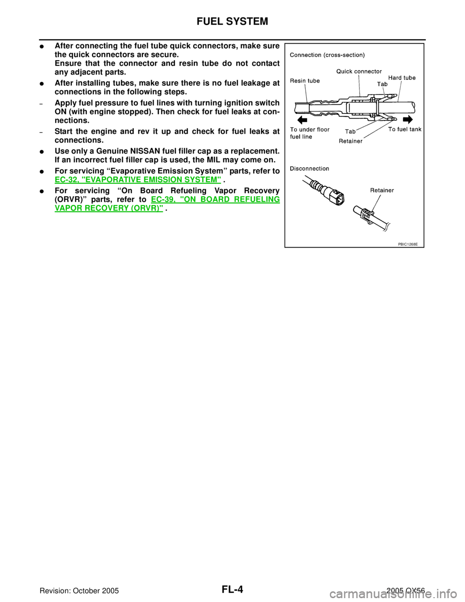
�After connecting the fuel tube quick connectors, make sure
the quick connectors are secure.
Ensure that the connector and resin tube do not contact
any adjacent parts.
�After installing tubes, make sure there is no fuel leakage at
connections in the following steps.
–Apply fuel pressure to fuel lines with turning ignition switch
ON (with engine stopped). Then check for fuel leaks at con-
nections.
–Start the engine and rev it up and check for fuel leaks at
connections.
�Use only a Genuine NISSAN fuel filler cap as a replacement.
If an incorrect fuel filler cap is used, the MIL may come on.
�For servicing “Evaporative Emission System” parts, refer to
EC-32, "
EVAPORATIVE EMISSION SYSTEM" .
�For servicing “On Board Refueling Vapor Recovery
(ORVR)” parts, refer to EC-39, "
ON BOARD REFUELING
VAPOR RECOVERY (ORVR)" .
PBIC1268E
Page 2070 of 3419

FUEL LEVEL SENSOR UNIT, FUEL FILTER AND FUEL PUMP ASSEMBLY
FL-5
C
D
E
F
G
H
I
J
K
L
MA
FL
Revision: October 20052005 QX56
FUEL LEVEL SENSOR UNIT, FUEL FILTER AND FUEL PUMP ASSEMBLYPFP:17042
Removal and InstallationEBS00M3S
REMOVAL
WA RN ING:
Follow the “General Precautions” before working on the fuel system. Refer to FL-3, "
General Precau-
tions" .
1. Remove the fuel filler cap to release the pressure from inside the fuel tank.
2. Check the fuel level on level gauge. If the fuel gauge indicates
more than the level as shown (full or almost full), drain the fuel
from the fuel tank until the fuel gauge indicates the level as
shown, or less.
�If the fuel pump does not operate, use the following procedure
to drain the fuel to the specified level.
a. Insert a suitable hose of less than 15 mm (0.59 in) diameter into
the fuel filler pipe through the fuel filler opening to drain the fuel
from fuel filler pipe.
b. Remove the LH rear wheel and tire. Refer to WT-7, "
Rotation" .
c. Remove the four clips and remove the rear fender protector,
front.
1. Inspection hole cover 2. Inspection hole cover O-ring 3. Lock ring
4. Fuel level sensor, fuel filter, and fuel
pump assembly5. Fuel tank 6. Fuel level sensor, fuel filter, and fuel
pump assembly O-ring
LBIA0381E
WBIA0390E
.
6. Install the fuel hose and tube to hose clamps.
7. Refill")