Page 1757 of 3419
EC-566Revision: October 2005
DTC P1572 ICC BRAKE SWITCH
2005 QX56
7. CHECK ICC BRAKE SWITCH INPUT SIGNAL CIRCUIT FOR OPEN AND SHORT
1. Disconnect ECM harness connector.
2. Check harness continuity between ICC brake switch terminal 2 and ECM terminal 108.
Refer Wiring Diagram.
3. Also check harness for short to ground and short to power.
OK or NG
OK >> GO TO 8.
NG >> Repair open circuit or short to ground or short to power in harness or connectors.
8. CHECK ICC BRAKE HOLD RELAY
Refer to EC-567, "
Component Inspection" .
OK >> GO TO 9.
NG >> Replace ICC brake hold relay.
9. CHECK ICC BRAKE SWITCH
Refer to EC-567, "
Component Inspection" .
OK or NG
OK >> GO TO 14.
NG >> Replace ICC brake switch.
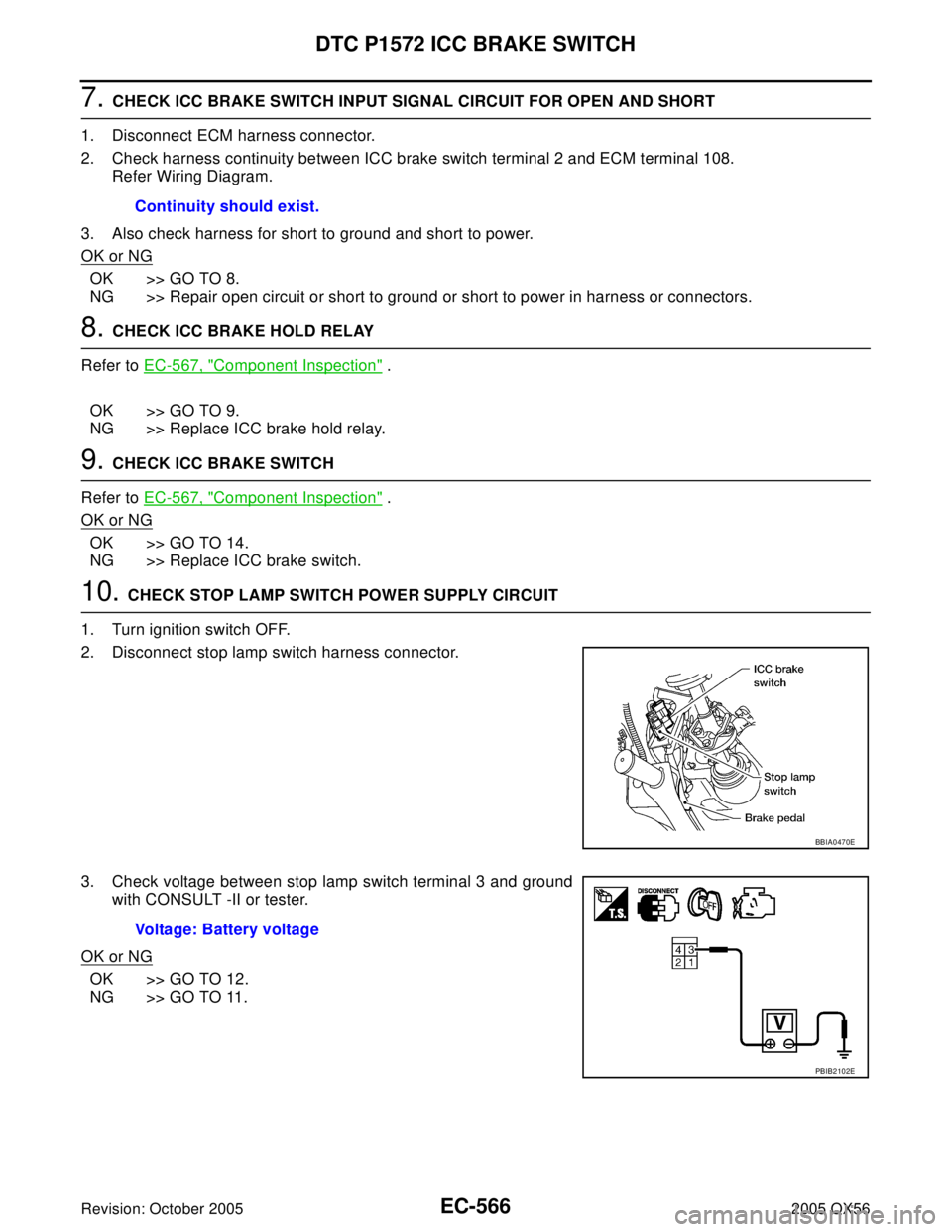
10. CHECK STOP LAMP SWITCH POWER SUPPLY CIRCUIT
1. Turn ignition switch OFF.
2. Disconnect stop lamp switch harness connector.
3. Check voltage between stop lamp switch terminal 3 and ground
with CONSULT -II or tester.
OK or NG
OK >> GO TO 12.
NG >> GO TO 11.Continuity should exist.
BBIA0470E
Voltage: Battery voltage
PBIB2102E
Page 1758 of 3419
DTC P1572 ICC BRAKE SWITCH
EC-567
C
D
E
F
G
H
I
J
K
L
MA
EC
Revision: October 20052005 QX56
11 . DETECT MALFUNCTIONING PART
Check the following.
�Harness connectors M31, E152
�Fuse block (J/B) No. 1 connector M60
�10A fuse
�Harness for open or short between stop lamp switch and battery
>> Repair open circuit or short to ground or short to power in harness or connectors.
12. CHECK STOP LAMP SWITCH INPUT SIGNAL CIRCUIT FOR OPEN AND SHORT
1. Disconnect ECM harness connector.
2. Check harness continuity between ECM terminal 101 and stop lamp switch terminal 4.
Refer to Wiring Diagram.
3. Also check harness for short to ground and short to power.
OK or NG
OK >> GO TO 13.
NG >> Repair open circuit or short to ground or short to power in harness or connectors.
13. CHECK STOP LAMP SWITCH
Refer to EC-567, "
Component Inspection"
OK or NG
OK >> GO TO 14.
NG >> Replace stop lamp switch.
14. CHECK INTERMITTENT INCIDENT
Refer to EC-156, "
TROUBLE DIAGNOSIS FOR INTERMITTENT INCIDENT" .
>>INSPECTION END
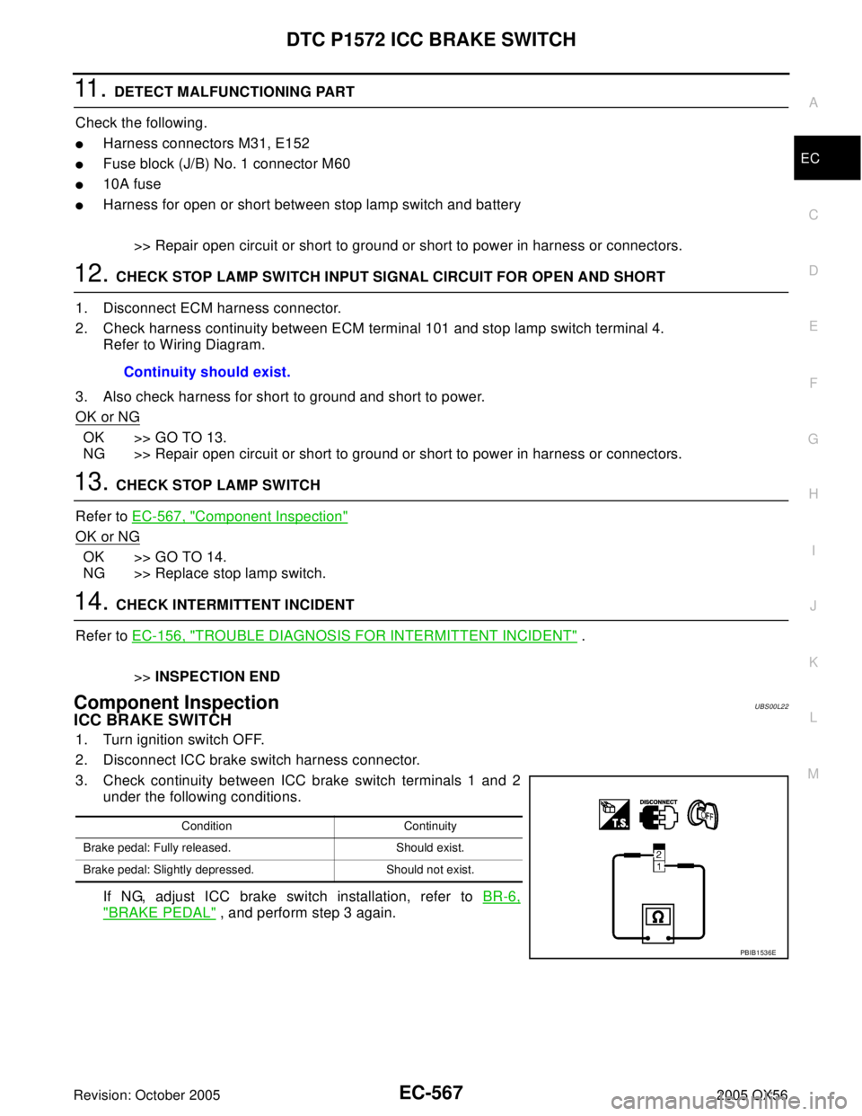
Component InspectionUBS00L22
ICC BRAKE SWITCH
1. Turn ignition switch OFF.
2. Disconnect ICC brake switch harness connector.
3. Check continuity between ICC brake switch terminals 1 and 2
under the following conditions.
If NG, adjust ICC brake switch installation, refer to BR-6,
"BRAKE PEDAL" , and perform step 3 again. Continuity should exist.
Condition Continuity
Brake pedal: Fully released. Should exist.
Brake pedal: Slightly depressed. Should not exist.
PBIB1536E
Page 1762 of 3419
DTC P1572 ASCD BRAKE SWITCH
EC-571
C
D
E
F
G
H
I
J
K
L
MA
EC
Revision: October 20052005 QX56
Wiring Diagram UBS00L17
BBWA1703E
Page 1765 of 3419
EC-574Revision: October 2005
DTC P1572 ASCD BRAKE SWITCH
2005 QX56
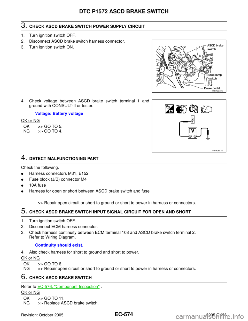
3. CHECK ASCD BRAKE SWITCH POWER SUPPLY CIRCUIT
1. Turn ignition switch OFF.
2. Disconnect ASCD brake switch harness connector.
3. Turn ignition switch ON.
4. Check voltage between ASCD brake switch terminal 1 and
ground with CONSULT-II or tester.
OK or NG
OK >> GO TO 5.
NG >> GO TO 4.
4. DETECT MALFUNCTIONING PART
Check the following.
�Harness connectors M31, E152
�Fuse block (J/B) connector M4
�10A fuse
�Harness for open or short between ASCD brake switch and fuse
>> Repair open circuit or short to ground or short to power in harness or connectors.
5. CHECK ASCD BRAKE SWITCH INPUT SIGNAL CIRCUIT FOR OPEN AND SHORT
1. Turn ignition switch OFF.
2. Disconnect ECM harness connector.
3. Check harness continuity between ECM terminal 108 and ASCD brake switch terminal 2.
Refer to Wiring Diagram.
4. Also check harness for short to ground and short to power.
OK or NG
OK >> GO TO 6.
NG >> Repair open circuit or short to ground or short to power in harness or connectors.
6. CHECK ASCD BRAKE SWITCH
Refer to EC-576, "
Component Inspection" .
OK or NG
OK >> GO TO 11.
NG >> Replace ASCD brake switch.
BBIA0373E
Voltage: Battery voltage
PBIB0857E
Continuity should exist.
Page 1766 of 3419
DTC P1572 ASCD BRAKE SWITCH
EC-575
C
D
E
F
G
H
I
J
K
L
MA
EC
Revision: October 20052005 QX56
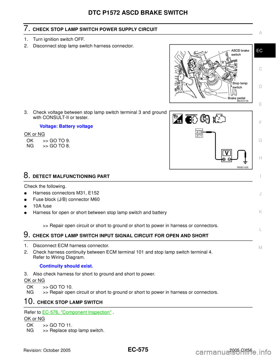
7. CHECK STOP LAMP SWITCH POWER SUPPLY CIRCUIT
1. Turn ignition switch OFF.
2. Disconnect stop lamp switch harness connector.
3. Check voltage between stop lamp switch terminal 3 and ground
with CONSULT-II or tester.
OK or NG
OK >> GO TO 9.
NG >> GO TO 8.
8. DETECT MALFUNCTIONING PART
Check the following.
�Harness connectors M31, E152
�Fuse block (J/B) connector M60
�10A fuse
�Harness for open or short between stop lamp switch and battery
>> Repair open circuit or short to ground or short to power in harness or connectors.
9. CHECK STOP LAMP SWITCH INPUT SIGNAL CIRCUIT FOR OPEN AND SHORT
1. Disconnect ECM harness connector.
2. Check harness continuity between ECM terminal 101 and stop lamp switch terminal 4.
Refer to Wiring Diagram.
3. Also check harness for short to ground and short to power.
OK or NG
OK >> GO TO 10.
NG >> Repair open circuit or short to ground or short to power in harness or connectors.
10. CHECK STOP LAMP SWITCH
Refer to EC-576, "
Component Inspection" .
OK or NG
OK >> GO TO 11.
NG >> Replace stop lamp switch.
BBIA0373E
Voltage: Battery voltage
PBIB2102E
Continuity should exist.
Page 1774 of 3419
DTC P1706 PNP SWITCH
EC-583
C
D
E
F
G
H
I
J
K
L
MA
EC
Revision: October 20052005 QX56
Wiring DiagramUBS00HBV
BBWA1704E
Page 1775 of 3419
EC-584Revision: October 2005
DTC P1706 PNP SWITCH
2005 QX56
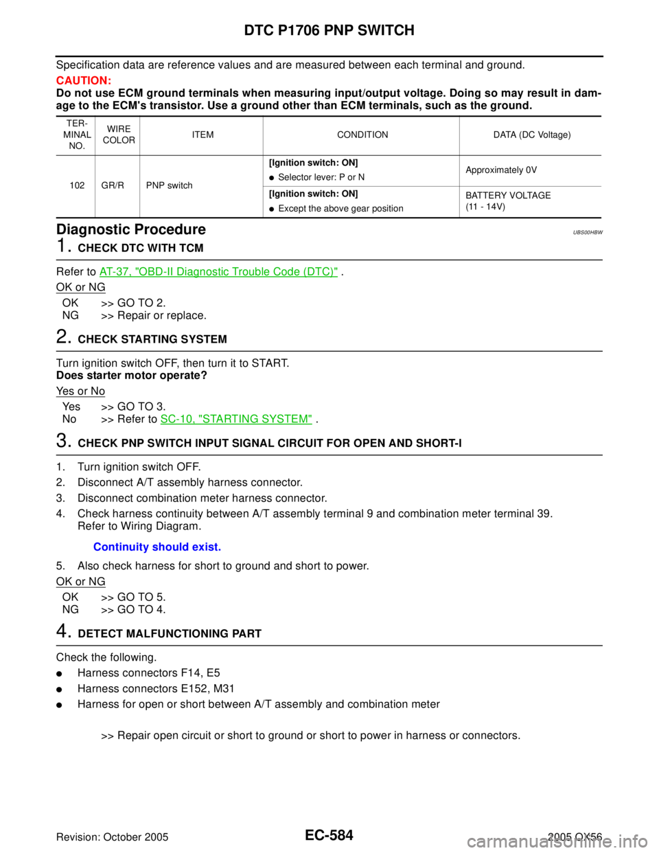
Specification data are reference values and are measured between each terminal and ground.
CAUTION:
Do not use ECM ground terminals when measuring input/output voltage. Doing so may result in dam-
age to the ECM's transistor. Use a ground other than ECM terminals, such as the ground.
Diagnostic ProcedureUBS00HBW
1. CHECK DTC WITH TCM
Refer to AT-37, "
OBD-II Diagnostic Trouble Code (DTC)" .
OK or NG
OK >> GO TO 2.
NG >> Repair or replace.
2. CHECK STARTING SYSTEM
Turn ignition switch OFF, then turn it to START.
Does starter motor operate?
Ye s o r N o
Yes >> GO TO 3.
No >> Refer to SC-10, "
STARTING SYSTEM" .
3. CHECK PNP SWITCH INPUT SIGNAL CIRCUIT FOR OPEN AND SHORT-I
1. Turn ignition switch OFF.
2. Disconnect A/T assembly harness connector.
3. Disconnect combination meter harness connector.
4. Check harness continuity between A/T assembly terminal 9 and combination meter terminal 39.
Refer to Wiring Diagram.
5. Also check harness for short to ground and short to power.
OK or NG
OK >> GO TO 5.
NG >> GO TO 4.
4. DETECT MALFUNCTIONING PART
Check the following.
�Harness connectors F14, E5
�Harness connectors E152, M31
�Harness for open or short between A/T assembly and combination meter
>> Repair open circuit or short to ground or short to power in harness or connectors.
TER-
MINAL
NO.WIRE
COLORITEM CONDITION DATA (DC Voltage)
102 GR/R PNP switch[Ignition switch: ON]
�Selector lever: P or NApproximately 0V
[Ignition switch: ON]
�Except the above gear positionBATTERY VOLTAGE
(11 - 14V)
Continuity should exist.
Page 1776 of 3419
DTC P1706 PNP SWITCH
EC-585
C
D
E
F
G
H
I
J
K
L
MA
EC
Revision: October 20052005 QX56
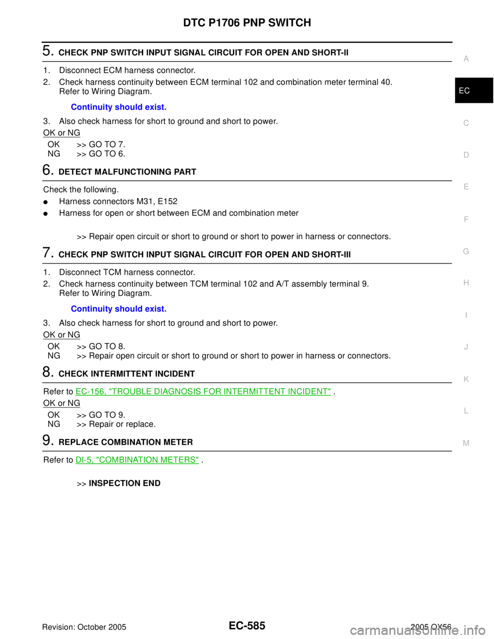
5. CHECK PNP SWITCH INPUT SIGNAL CIRCUIT FOR OPEN AND SHORT-II
1. Disconnect ECM harness connector.
2. Check harness continuity between ECM terminal 102 and combination meter terminal 40.
Refer to Wiring Diagram.
3. Also check harness for short to ground and short to power.
OK or NG
OK >> GO TO 7.
NG >> GO TO 6.
6. DETECT MALFUNCTIONING PART
Check the following.
�Harness connectors M31, E152
�Harness for open or short between ECM and combination meter
>> Repair open circuit or short to ground or short to power in harness or connectors.
7. CHECK PNP SWITCH INPUT SIGNAL CIRCUIT FOR OPEN AND SHORT-III
1. Disconnect TCM harness connector.
2. Check harness continuity between TCM terminal 102 and A/T assembly terminal 9.
Refer to Wiring Diagram.
3. Also check harness for short to ground and short to power.
OK or NG
OK >> GO TO 8.
NG >> Repair open circuit or short to ground or short to power in harness or connectors.
8. CHECK INTERMITTENT INCIDENT
Refer to EC-156, "
TROUBLE DIAGNOSIS FOR INTERMITTENT INCIDENT" .
OK or NG
OK >> GO TO 9.
NG >> Repair or replace.
9. REPLACE COMBINATION METER
Refer to DI-5, "
COMBINATION METERS" .
>>INSPECTION END Continuity should exist.
Continuity should exist.