Page 1158 of 3419

WARNING CHIME
DI-55
C
D
E
F
G
H
I
J
L
MA
B
DI
Revision: October 20052005 QX56
5. CHECK KEY SWITCH CIRCUIT
1. Disconnect BCM.
2. Check continuity between BCM harness connector M18 terminal
37 (B/R) and key switch and key lock solenoid harness connec-
tor M27 terminal 4 (B/R).
3. Check continuity between BCM harness connector M18 terminal
37 (B/R) and ground.
OK or NG
OK >> GO TO 6.
NG >> Repair harness or connector.
6. CHECK KEY SWITCH POWER SUPPLY CIRCUIT
Check voltage between key switch and key lock solenoid harness
connector M27 terminal 3 (Y/R) and ground.
OK or NG
OK >> Replace the BCM. Refer to BCS-20, "Removal and
Installation of BCM" .
NG >> Check harness for open or short between fuse and key
switch and key lock solenoid.
Light Warning Chime Does Not OperateEKS00BD0
1. CHECK WARNING CHIME OPERATION
Check key warning chime and seat belt warning chime functions.
Do key warning chime and seat belt warning chime sound?
YES >> GO TO 2.
NO >> Go to DI-51, "
All Warning Chimes Do Not Operate" .
2. CHECK BCM INPUT SIGNAL
With CONSULT-II
1. Select "BCM".
2. With "DATA MONITOR" of "BUZZER", confirm "LIGHT SW 1ST"
status changes when the lighting switch is moved from ON (1st
position) to OFF.
Without CONSULT-II
Check combination switch. Refer to LT-98, "
Combination Switch
Reading Function" .
OK or NG
OK >> Replace the BCM. Refer to BCS-20, "Removal and Installation of BCM" .
NG >> Check lighting switch. Refer to LT- 9 8 , "
Combination Switch Reading Function" . Continuity should exist.
Continuity should not exist.
WKIA2074E
Battery voltage should exist.
WKIA2075E
Lighting switch ON (1st position) : LIGHT SW 1ST ON
Lighting switch OFF : LIGHT SW 1ST OFF
WKIA1877E
Page 1159 of 3419
DI-56
WARNING CHIME
Revision: October 20052005 QX56
Seat Belt Warning Chime Does Not OperateEKS00BD1
1. CHECK WARNING CHIME OPERATION
1. With key removed from the ignition and the front door LH open, turn the lighting switch to 1st or 2nd posi-
tion.
2. Return lighting switch to OFF position, and insert key into ignition.
Does warning chime sound for both steps?
YES >> GO TO 2.
NO >> Go to DI-51, "
All Warning Chimes Do Not Operate" .
2. CHECK SEAT BELT WARNING LAMP OPERATION
Turn ignition switch ON. Buckle and unbuckle the driver seat belt while watching seat belt warning lamp.
OK or NG
OK >> Replace the BCM. Refer to BCS-20, "Removal and Installation of BCM" .
NG >> GO TO 3.
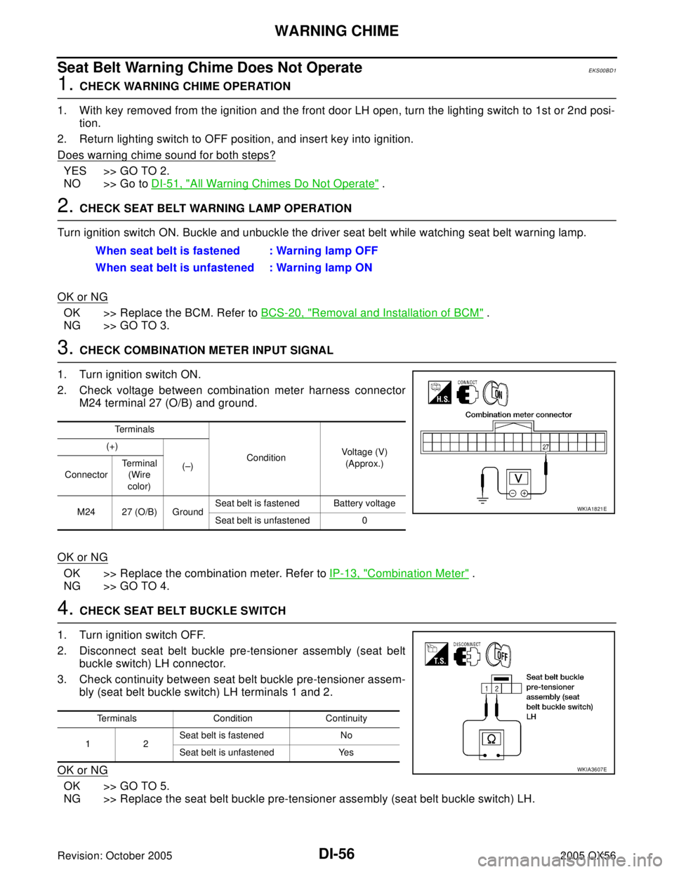
3. CHECK COMBINATION METER INPUT SIGNAL
1. Turn ignition switch ON.
2. Check voltage between combination meter harness connector
M24 terminal 27 (O/B) and ground.
OK or NG
OK >> Replace the combination meter. Refer to IP-13, "Combination Meter" .
NG >> GO TO 4.
4. CHECK SEAT BELT BUCKLE SWITCH
1. Turn ignition switch OFF.
2. Disconnect seat belt buckle pre-tensioner assembly (seat belt
buckle switch) LH connector.
3. Check continuity between seat belt buckle pre-tensioner assem-
bly (seat belt buckle switch) LH terminals 1 and 2.
OK or NG
OK >> GO TO 5.
NG >> Replace the seat belt buckle pre-tensioner assembly (seat belt buckle switch) LH.When seat belt is fastened : Warning lamp OFF
When seat belt is unfastened : Warning lamp ON
Terminals
ConditionVoltage (V)
(Approx.) (+)
(–)
ConnectorTe r m i n a l
(Wire
color)
M24 27 (O/B) GroundSeat belt is fastened Battery voltage
Seat belt is unfastened 0
WKIA1821E
Terminals Condition Continuity
12Seat belt is fastened No
Seat belt is unfastened Yes
WKIA3607E
Page 1161 of 3419
DI-58
REAR SONAR SYSTEM
Revision: October 20052005 QX56
REAR SONAR SYSTEMPFP:28532
Component Parts and Harness Connector LocationEKS00BD2
1. Back-up lamp relay E45 2. Battery 3. Sonar buzzer M117
4. Rear sonar system OFF switch M116 5. Sonar control unit B56 6. Rear sonar sensor LH outer C102
7. Rear sonar sensor LH inner C103 8. Rear sonar sensor RH inner C104 9. Rear sonar sensor RH outer C105
10. A/T assembly F9
LKIA0693E
Page 1169 of 3419
DI-66
REAR SONAR SYSTEM
Revision: October 20052005 QX56
Preliminary CheckEKS00BD9
INSPECTION FOR POWER SUPPLY AND GROUND CIRCUIT
1. CHECK FUSE
Check for blown rear sonar system fuse.
Refer to DI-61, "
Wiring Diagram — SONAR —" .
OK or NG
OK >> GO TO 2.
NG >> If fuse is blown, be sure to eliminate cause of problem before installing new fuse. Refer to PG-4,
"POWER SUPPLY ROUTING CIRCUIT" .
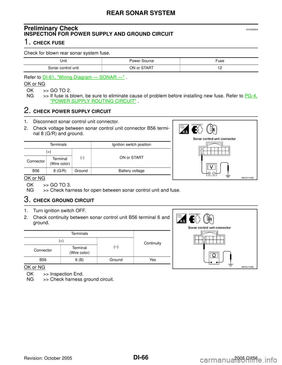
2. CHECK POWER SUPPLY CIRCUIT
1. Disconnect sonar control unit connector.
2. Check voltage between sonar control unit connector B56 termi-
nal 8 (G/R) and ground.
OK or NG
OK >> GO TO 3.
NG >> Check harness for open between sonar control unit and fuse.
3. CHECK GROUND CIRCUIT
1. Turn ignition switch OFF.
2. Check continuity between sonar control unit B56 terminal 6 and
ground.
OK or NG
OK >> Inspection End.
NG >> Check harness ground circuit.
Unit Power Source Fuse
Sonar control unit ON or START 12
Terminals Ignition switch position
(+)
(-) ON or START
ConnectorTe r m i n a l
(Wire color)
B56 8 (G/R) Ground Battery voltage
WKIA1145E
Te r m i n a l s
Continuity (+)
(–)
ConnectorTerminal
(Wire color)
B56 6 (B) Ground Yes
WKIA1146E
Page 1171 of 3419
DI-68
REAR SONAR SYSTEM
Revision: October 20052005 QX56
Component InspectionEKS00BDB
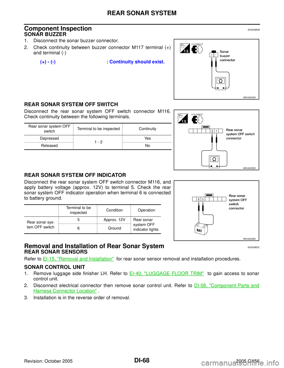
SONAR BUZZER
1. Disconnect the sonar buzzer connector.
2. Check continuity between buzzer connector M117 terminal (+)
and terminal (-)
REAR SONAR SYSTEM OFF SWITCH
Disconnect the rear sonar system OFF switch connector M116.
Check continuity between the following terminals.
REAR SONAR SYSTEM OFF INDICATOR
Disconnect the rear sonar system OFF switch connector M116, and
apply battery voltage (approx. 12V) to terminal 5. Check the rear
sonar system OFF indicator operation when terminal 6 is connected
to battery ground.
Removal and Installation of Rear Sonar SystemEKS00BDC
REAR SONAR SENSORS
Refer to EI-15, "Removal and Installation" for rear sonar sensor removal and installation procedures.
SONAR CONTROL UNIT
1. Remove luggage side finisher LH. Refer to EI-40, "LUGGAGE FLOOR TRIM" to gain access to sonar
control unit.
2. Disconnect electrical connector then remove sonar control unit. Refer to DI-58, "
Component Parts and
Harness Connector Location" .
3. Installation is in the reverse order of removal.(+) - (-) : Continuity should exist.
WKIA2024E
Rear sonar system OFF
switch Terminal to be inspected Continuity
Depressed
1 - 2Ye s
Released No
WKIA2025E
Terminal to be
inspectedCondition Operation
Rear sonar sys-
tem OFF switch5 Approx. 12V Rear sonar
system OFF
indicator lights 6 Ground
WKIA2026E
Page 1180 of 3419
REAR VIEW MONITOR
DI-77
C
D
E
F
G
H
I
J
L
MA
B
DI
Revision: October 20052005 QX56
Terminals and Reference Value for Rear View Camera Control UnitEKS00BDJ
Te r m i n a l
No.Wire
colorItemCondition
Reference value (V)
(Approx.) Ignition
switchOperation
1 Y Battery power OFF — Battery voltage
2 V ACC power ACC — Battery voltage
3 B Ground ON — 0
4 G/W Reverse signal input ONA/T selector lever R position Battery voltage
A/T selector lever in other than R
position0
5BRAV Control ONA/T selector lever R position 0
—0
6G/WDDL — — —
8 Y Camera power output ON A/T selector lever R position 6
9 — Camera image input (–) ON — 0
10 G Camera image input (+) ON A/T selector lever R position
11 — Shield ground — — —
12 W Composite image output ON A/T selector lever R position
SKIA4894E
SKIA4896E
Page 1185 of 3419
DI-82
REAR VIEW MONITOR
Revision: October 20052005 QX56
Power Supply and Ground Circuit InspectionEKS00BDM
1. CHECK FUSES
Check for blown rear view camera system fuses.
OK or NG
OK >> GO TO 2.
NG >> If fuse is blown, be sure to eliminate cause of problem before installing new fuse. Refer to PG-4,
"POWER SUPPLY ROUTING CIRCUIT" .
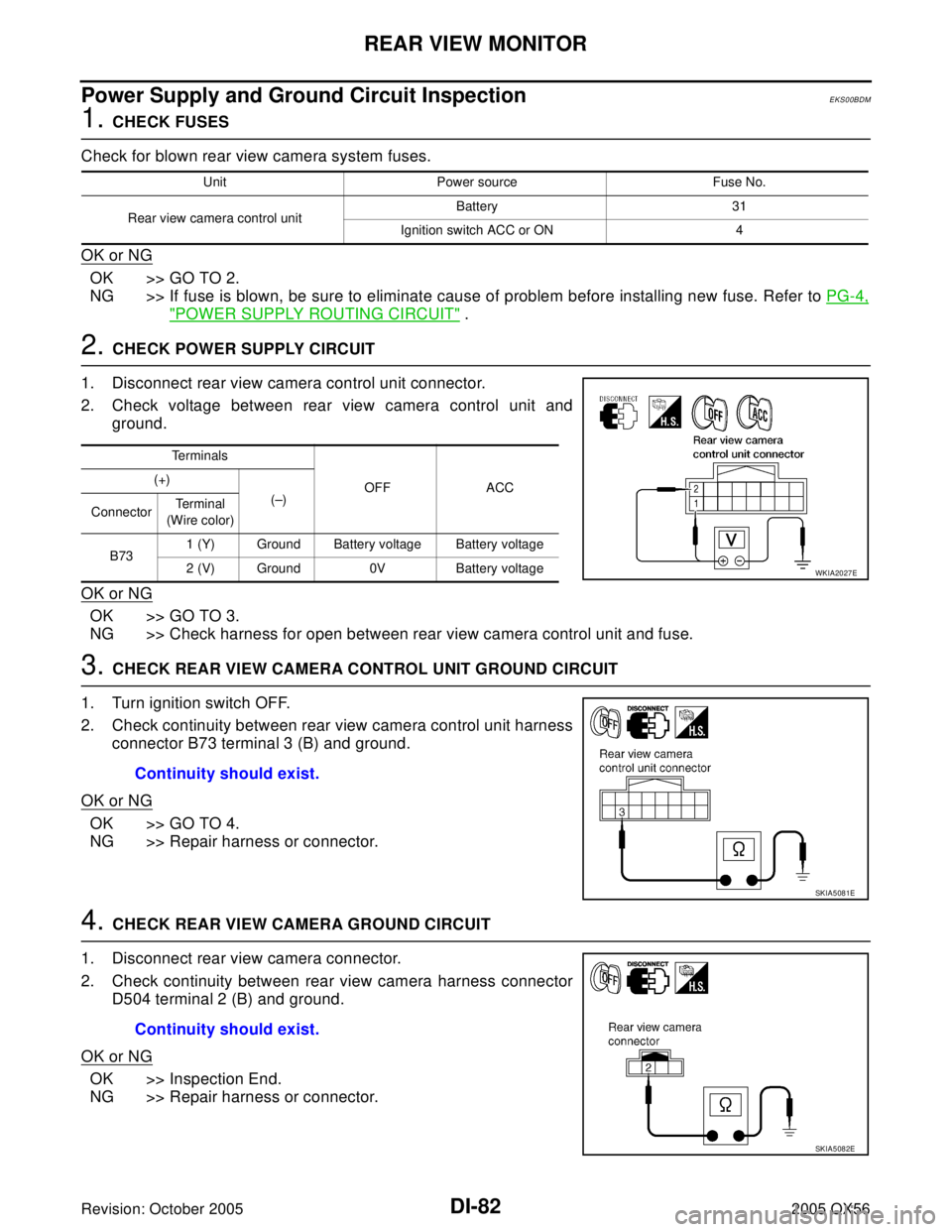
2. CHECK POWER SUPPLY CIRCUIT
1. Disconnect rear view camera control unit connector.
2. Check voltage between rear view camera control unit and
ground.
OK or NG
OK >> GO TO 3.
NG >> Check harness for open between rear view camera control unit and fuse.
3. CHECK REAR VIEW CAMERA CONTROL UNIT GROUND CIRCUIT
1. Turn ignition switch OFF.
2. Check continuity between rear view camera control unit harness
connector B73 terminal 3 (B) and ground.
OK or NG
OK >> GO TO 4.
NG >> Repair harness or connector.
4. CHECK REAR VIEW CAMERA GROUND CIRCUIT
1. Disconnect rear view camera connector.
2. Check continuity between rear view camera harness connector
D504 terminal 2 (B) and ground.
OK or NG
OK >> Inspection End.
NG >> Repair harness or connector.
Unit Power source Fuse No.
Rear view camera control unitBattery 31
Ignition switch ACC or ON 4
Te r m i n a l s
OFF ACC (+)
(–)
ConnectorTe r m i n a l
(Wire color)
B731 (Y) Ground Battery voltage Battery voltage
2 (V) Ground 0V Battery voltage
WKIA2027E
Continuity should exist.
SKIA5081E
Continuity should exist.
SKIA5082E
Page 1186 of 3419
REAR VIEW MONITOR
DI-83
C
D
E
F
G
H
I
J
L
MA
B
DI
Revision: October 20052005 QX56
Rear View Is Not Displayed With The A/T Selector Lever In R PositionEKS00BDN
1. BACK-UP LAMP INSPECTION
1. Turn ignition switch ON.
2. Shift A/T selector lever to R position.
Does back-up lamp illuminate?
YES >> GO TO 2.
NO >> Check back-up lamp system. Refer to LT-106, "
BACK-UP LAMP" .
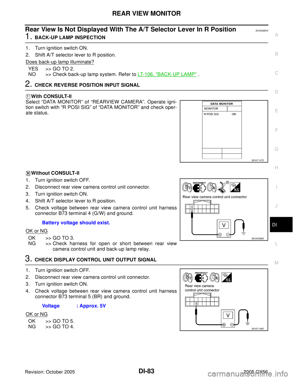
2. CHECK REVERSE POSITION INPUT SIGNAL
With CONSULT-II
Select “DATA MONITOR” of “REARVIEW CAMERA”. Operate igni-
tion switch with “R POSI SIG” of “DATA MONITOR” and check oper-
ate status.
Without CONSULT-II
1. Turn ignition switch OFF.
2. Disconnect rear view camera control unit connector.
3. Turn ignition switch ON.
4. Shift A/T selector lever to R position.
5. Check voltage between rear view camera control unit harness
connector B73 terminal 4 (G/W) and ground.
OK or NG
OK >> GO TO 3.
NG >> Check harness for open or short between rear view
camera control unit and back-up lamp relay.
3. CHECK DISPLAY CONTROL UNIT OUTPUT SIGNAL
1. Turn ignition switch OFF.
2. Disconnect rear view camera control unit connector.
3. Turn ignition switch ON.
4. Check voltage between rear view camera control unit harness
connector B73 terminal 5 (BR) and ground.
OK or NG
OK >> GO TO 5.
NG >> GO TO 4.
SKIA7147E
Battery voltage should exist.
SKIA5086E
Voltage : Approx. 5V
SKIA7148E