2005 INFINITI FX35 Heater core
[x] Cancel search: Heater corePage 440 of 4731

ATC-3
C
D E
F
G H
I
K L
M A
B
AT C
Revision: 2005 July 2005 FX
COMPONENT INSPECTION ...........................
.. 112
Intake Sensor Circuit ........................................... .. 113
COMPONENT DESCRIPTION ........................ .. 113
DIAGNOSIS PROCEDURE FOR INTAKE SEN-
SOR ................................................................. .. 113
COMPONENT INSPECTION ........................... .. 114
CONTROLLER ...................................................... ..115
Removal and Installation of A/C and AV Switch .. .. 115
REMOVAL ........................................................ .. 115
INSTALLATION ................................................ .. 115
AUTO AMP ............................................................ ..116
Removal and Installation of Unified Meter and A/C
Amp. .................................................................... .. 116
REMOVAL ........................................................ .. 116
INSTALLATION ................................................ .. 116
AMBIENT SENSOR ............................................... ..117
Removal and Installation ..................................... .. 117
REMOVAL ........................................................ .. 117
INSTALLATION ................................................ .. 117
IN-VEHICLE SENSOR ........................................... ..118
Removal and Installation ..................................... .. 118
REMOVAL ........................................................ .. 118
INSTALLATION ................................................ .. 118
SUNLOAD SENSOR ............................................. ..119
Removal and Installation ..................................... .. 119
REMOVAL ........................................................ .. 119
INSTALLATION ................................................ .. 119
INTAKE SENSOR .................................................. . 120
Removal and Installation ..................................... . 120
REMOVAL ........................................................ . 120
INSTALLATION ................................................ . 120
BLOWER UNIT ...................................................... . 121
Removal and Installation ..................................... . 121
REMOVAL ........................................................ . 121
INSTALLATION ................................................ . 121
Disassembly and Assembly ................................ . 122
BLOWER MOTOR ................................................. . 123
Removal and Installation ..................................... . 123
REMOVAL ........................................................ . 123
INSTALLATION ................................................ . 123
INTAKE DOOR MOTOR ........................................ . 124
Removal and Installation ..................................... . 124
REMOVAL ........................................................ . 124
INSTALLATION ................................................ . 124
IN-CABIN MICROFILTER ...................................... . 125
Removal and Installation ..................................... . 125
FUNCTION ....................................................... . 125
REPLACEMENT TIMING ................................. . 125
REPLACEMENT PROCEDURES .................... . 125
HEATER & COOLING UNIT ASSEMBLY ............. . 126
Removal and Installation ..................................... . 126
REMOVAL ........................................................ . 126
INSTALLATION ................................................ . 127
Disassembly and Assembly ................................ . 129
MODE DOOR MOTOR .......................................... . 131
Removal and Installation ..................................... . 131
REMOVAL ........................................................ . 131
INSTALLATION ................................................ . 131 AIR MIX DOOR MOTOR ........................................
.132
Removal and Installation ..................................... .132
REMOVAL ........................................................ .132
INSTALLATION ................................................ .132
HEATER CORE ...................................................... .133
Removal and Installation ..................................... .133
REMOVAL ........................................................ .133
INSTALLATION ................................................ .133
DUCTS AND GRILLES .......................................... .134
Removal and Installation ..................................... .134
REMOVAL ........................................................ .134
INSTALLATION ................................................ .137
REFRIGERANT LINES .......................................... .138
HFC-134a (R-134a) Service Procedure .............. .138
SETTING OF SERVICE TOOLS AND EQUIP-
MENT ............................................................... .138
Components ........................................................ .140
VQ35DE ........................................................... .140
VK45DE ............................................................ .141
Removal and Installation of Compressor ............. .141
REMOVAL ........................................................ .141
INSTALLATION ................................................ .143
Removal and Installation of Compressor Clutch . .144
REMOVAL ........................................................ .144
INSTALLATION ................................................ .146
Removal and Installation of Low-Pressure Flexible
Hose .................................................................... .148
REMOVAL ........................................................ .148
INSTALLATION ................................................ .149
Removal and Installation of High-Pressure Flexible
Hose .................................................................... .149
REMOVAL ........................................................ .149
INSTALLATION ................................................ .150
Removal and Installation of Low-Pressure Pipe 1
(Engine Compartment) ........................................ .150
REMOVAL ........................................................ .150
INSTALLATION ................................................ .151
Removal and Installation of High-Pressure Pipe 1
and 2 (Engine Compartment) .............................. .151
REMOVAL ........................................................ .151
INSTALLATION ................................................ .152
Removal and Installation of Low-Pressure Pipe 2
and High-Pressure Pipe 3 ................................... .152
REMOVAL ........................................................ .152
INSTALLATION ................................................ .153
Removal and Installation of Liquid Tank .............. .154
REMOVAL ........................................................ .154
INSTALLATION ................................................ .154
Removal and Installation of Condenser ............... .155
REMOVAL ........................................................ .155
INSTALLATION ................................................ .155
Removal and Installation of Refrigerant Pressure
Sensor ................................................................. .156
REMOVAL ........................................................ .156
INSTALLATION ................................................ .156
Removal and Installation of Evaporator ............... .156
REMOVAL ........................................................ .156
INSTALLATION ................................................ .156
Removal and Installation of Expansion Valve ...... .157
Page 563 of 4731
ATC-126
HEATER & COOLING UNIT ASSEMBLY
Revision: 2005 July 2005 FX
HEATER & COOLING UNIT ASSEMBLYPFP:27110
Removal and InstallationAJS0015J
REMOVAL
1. Use a refrigerant collecting equipment (for HFC-134a) to discharge refrigerant.
2. Drain coolant from cooling system. Refer to CO-11, "
Changing Engine Coolant" (VQ35DE) or CO-37,
"Changing Engine Coolant" (VK45DE).
3. Remove cowl top cover. Refer to EI-23, "
COWL TOP" .
4. Remove high-pressure pipe 2 mounting clip.
5. Remove low-pressure flexible hose bracket mounting bolt.
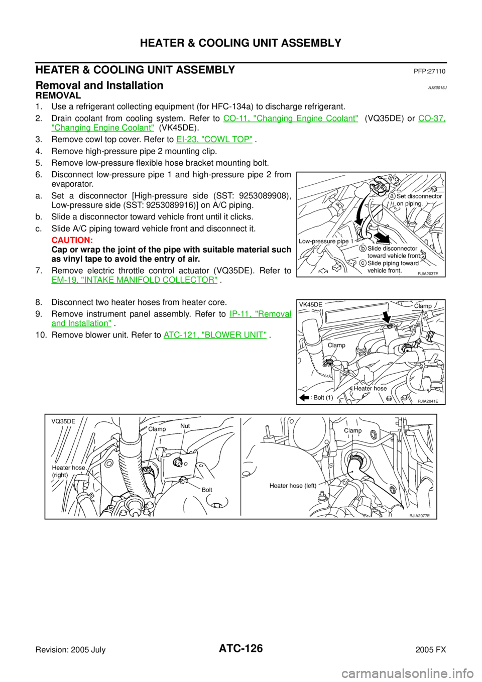
6. Disconnect low-pressure pipe 1 and high-pressure pipe 2 from evaporator.
a. Set a disconnector [High-pressure side (SST: 9253089908), Low-pressure side (SST: 9253089916)] on A/C piping.
b. Slide a disconnector toward vehicle front until it clicks.
c. Slide A/C piping toward vehicle front and disconnect it. CAUTION:
Cap or wrap the joint of the pipe with suitable material such
as vinyl tape to avoid the entry of air.
7. Remove electric throttle control actuator (VQ35DE). Refer to EM-19, "
INTAKE MANIFOLD COLLECTOR" .
8. Disconnect two heater hoses from heater core.
9. Remove instrument panel assembly. Refer to IP-11, "
Removal
and Installation" .
10. Remove blower unit. Refer to ATC-121, "
BLOWER UNIT" .
RJIA2037E
RJIA2041E
RJIA2077E
Page 566 of 4731
HEATER & COOLING UNIT ASSEMBLY ATC-129
C
D E
F
G H
I
K L
M A
B
AT C
Revision: 2005 July 2005 FX
Disassembly and AssemblyAJS0015K
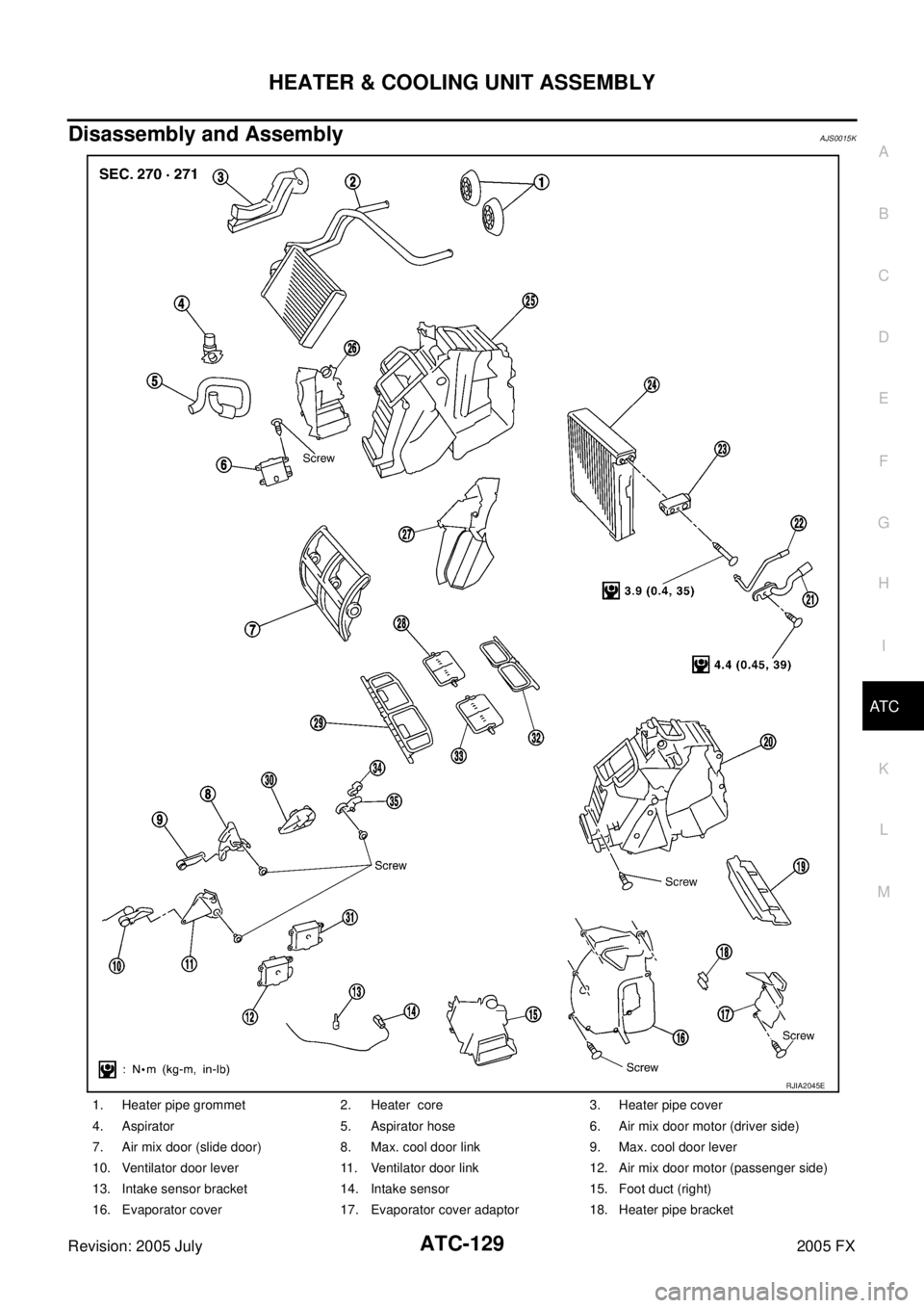
1. Heater pipe grommet 2. Heater core 3. Heater pipe cover
4. Aspirator 5. Aspirator hose 6. Air mix door motor (driver side)
7. Air mix door (slide door) 8. Max. cool door link 9. Max. cool door lever
10. Ventilator door lever 11. Ventilator door link 12. Air mix door motor (passenger side)
13. Intake sensor bracket 14. Intake sensor 15. Foot duct (right)
16. Evaporator cover 17. Evaporator cover adaptor 18. Heater pipe bracket
RJIA2045E
Page 570 of 4731
HEATER CORE ATC-133
C
D E
F
G H
I
K L
M A
B
AT C
Revision: 2005 July 2005 FX
HEATER COREPFP:27140
Removal and InstallationAJS0015N
REMOVAL
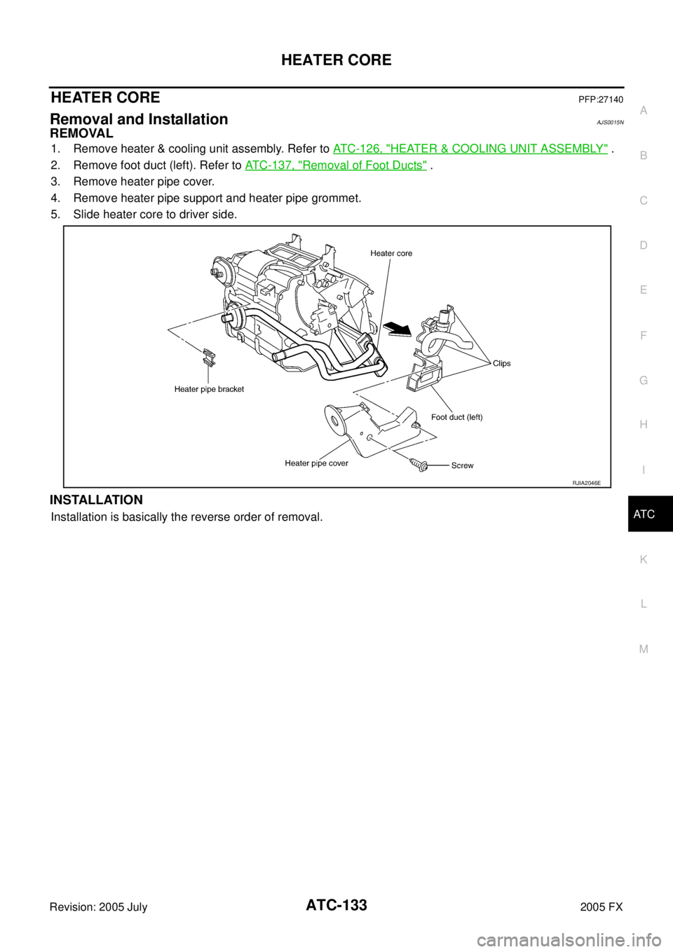
1. Remove heater & cooling unit assembly. Refer to ATC-126, "HEATER & COOLING UNIT ASSEMBLY" .
2. Remove foot duct (left). Refer to ATC-137, "
Removal of Foot Ducts" .
3. Remove heater pipe cover.
4. Remove heater pipe support and heater pipe grommet.
5. Slide heater core to driver side.
INSTALLATION
Installation is basically the reverse order of removal.
RJIA2046E
Page 3398 of 4731
IDX-5
A
C
D E
F
G H
I
J
K L
B
IDX
ALPHABETICAL INDEX
Hazard warning lamp ..........................................
LT-91
Headlamp aiming control .................................... LT-75
Headlamp leveler - See Headlamp aiming control .......
LT-75
Headlining - See Roof trim .................................. EI-41
Heated oxygen sensor 1 (bank 1) .... EC-935, EC-944,
EC-956
, EC-1174, EC-1180
Heated oxygen sensor 1 (bank 2) .... EC-935, EC-944,
EC-956
, EC-1174, EC-1180
Heated oxygen sensor 1 heater (bank 1) ........ EC-877
Heated oxygen sensor 1 heater (bank 2) ........ EC-877
Heated oxygen sensor 2 (bank 1) .... EC-228, EC-237,
EC-442
, EC-453, EC-966, EC-975, EC-1187, EC-1198
Heated oxygen sensor 2 (bank 2) .... EC-228, EC-237,
EC-442
, EC-453, EC-966, EC-975, EC-1187, EC-1198
Heated oxygen sensor 2 heater (bank 1) ....... EC-178,
EC-885
Heated oxygen sensor 2 heater (bank 2) ....... EC-178,
EC-885
Heated seat ....................................................... SE-97
Heater and cooling unit (Heater core) ........... ATC-126
HFC134a (R134a) system precaution ............... ATC-6
HFC134a (R134a) system service procedure ATC-138
HFC134a (R134a) system service tools .......... ATC-18
HFC134a system service equipment precaution ..........
ATC-13
High and low reverse clutch solenoid valve .... AT-162,
AT-164
Hood ................................................................... BL-13
Horn ................................................................. WW-59
HORN - Wiring diagram ................................... WW-59
HSEAT - Wiring diagram ................................... SE-98
I
IATS - Wiring diagram ....................... EC-205
, EC-911
ICC - Wiring diagram ....................................... ACS-20
ICC/BS - Wiring diagram ................. EC-590, EC-1264
ICC/SW - Wiring diagram ................ EC-576, EC-1249
ICCBOF - Wiring diagram ................ EC-681, EC-1371
Idle air volume learning ....................... EC-97, EC-787
Idle mixture ratio .............................................. EC-775
Idle speed .......................................... EC-769, EC-774
Idle speed control (ISC) .... EC-393, EC-395, EC-1125,
EC-1127
Ignition coil ....................................... EC-648, EC-1339
Ignition coil(VK45DE) ...................................... EM-189
Ignition coil(VQ35DE) ........................................ EM-42
Ignition control system ..................... EC-648, EC-1339
Ignition key hole illumination ............................. LT-155
Ignition timing .................................... EC-769, EC-774
IGNSYS - Wiring diagram ................ EC-649, EC-1340
Illumination control ............................................ LT-202
In vehicle sensor ........................... ATC-107, ATC-118
INF/D - Wring diagram ....................................... AV-63
INJECT - Wiring diagram ................. EC-662, EC-1352
Injector ............................................. EC-661, EC-1351
Input clutch solenoid valve ................. AT-150, AT-152
Instrument panel .................................................. IP-10
Intake air temperature sensor ........... EC-203, EC-223,
EC-909
, EC-930
Intake door control linkage adjustment ............ ATC-78
Intake door motor ............................ ATC-76, ATC-124
Intake manifold collector(VQ35DE) .................. EM-19
Intake manifold(VK45DE) ............................... EM-178
Intake manifold(VQ35DE) ................................. EM-24
Intake sensor ................................ ATC-113, ATC-120
Intake valve timing control (Bank 1) ... EC-174, EC-865
Intake valve timing control (Bank 2) ... EC-174, EC-865
Intake valve timing control position sensor (Bank 1) ....
EC-1166
Intake valve timing control position sensor (Bank 2) ....
EC-1166
Intake valve timing control solenoid valve (Bank 1) ......
EC-417
, EC-1141
Intake valve timing control solenoid valve (Bank 2) ......
EC-417
, EC-1141
Integrated homelink transmitter ....................... BL-235
Intelligent cruise control (ICC) system .............. ACS-6
Interior ................................................................. EI-36
Interior lamp ...................................................... LT-159
IPDM (Intelligent power distribution module engine
room) ................................................................. PG-18
IVCB1 - Wiring diagram ................... EC-418, EC-1142
IVCB2 - Wiring diagram ................... EC-420, EC-1144
IVCSB1 - Wiring diagram ............................... EC-1167
IVCSB2 - Wiring diagram ............................... EC-1169
IVIS (Infiniti vehicle immobilizer system) precautions ...
GI-3
IVTB1 - Wiring diagram ................................... EC-868
IVTB2 - Wiring diagram ................................... EC-870
K
Knock sensor (KS) ........................... EC-295
, EC-1031
KS - Wiring diagram ......................... EC-296, EC-1032
L
LAN system circuit ........................................... ATC-66
Lane Departure Warning System ....................... DI-82
Laser beam aiming adjustment ....................... ACS-12
Latch (lower anchors and tether for children) system ...
SB-9
LDW .................................................................... DI-82
LDW - Wiring Diagram ........................................ DI-95
Line pressure solenoid valve ........................... AT-129
Line pressure test (A/T) ..................................... AT-54
Liquid gasket application ......................... EM-6, LU-21
Liquid gasket application(VQ35DE) ........... LU-3, CO-3
Location of electrical units ................................. PG-70
Low coast brake solenoid valve ......... AT-166, AT-168
Low tire pressure warning system ...................... WT-7
Lubricant (R134a) A/C ..................................... ATC-27
Lubrication circuit (engine)(VK45DE) ................ LU-23
Lubrication circuit (engine)(VQ35DE) .................. LU-5
Lubrication oil A/C .......................................... ATC-162