Page 2942 of 4731
![INFINITI FX35 2005 Service Manual CYLINDER HEAD EM-107
[VQ35DE]
C
D E
F
G H
I
J
K L
M A
EM
Revision: 2005 July 2005 FX
8. Install valve collet.
�Compress valve spring with the valve spring compressor, the
attachment and](/manual-img/42/57020/w960_57020-2941.png "INFINITI FX35 2005 Service Manual CYLINDER HEAD EM-107
[VQ35DE]
C
D E
F
G H
I
J
K L
M A
EM
Revision: 2005 July 2005 FX
8. Install valve collet.
�Compress valve spring with the valve spring compressor, the
attachment and")
CYLINDER HEAD EM-107
[VQ35DE]
C
D E
F
G H
I
J
K L
M A
EM
Revision: 2005 July 2005 FX
8. Install valve collet.
�Compress valve spring with the valve spring compressor, the
attachment and the adapter [SST]. Install valve collet with a
magnet hand.
CAUTION:
When working, take care not to damage valve lifter holes.
�Tap valve stem edge lightly with plastic hammer after installa-
tion to check its installed condition.
9. Install valve lifter.
�Install it in the original position.
10. Install spark plug tube.
�Press-fit spark plug tube as follows:
a. Remove old liquid gasket adhering to cylinder head mounting hole.
b. Apply sealant to area within approximately 12 mm (0.47 in) from edge of spark plug tube press-fit side. Use Genuine High Strength Locking Sealant or equivalent. Refer to GI-48, "
RECOMMENDED
CHEMICAL PRODUCTS AND SEALANTS" .
c. Using drift, press-fit spark plug tube so that its height “H” is as specified in the figure.
CAUTION:
�When press-fitting, take care not to deform spark plug
tube.
�After press-fitting, wipe off liquid gasket protruding onto
cylinder-head upper face.
11. Install spark plug with spark plug wrench (commercial service tool).
Inspection After DisassemblyABS004XA
VALVE DIMENSIONS
�Check the dimensions of each valve. For the dimensions, refer to EM-154, "Valve Dimensions" .
�If dimensions are out of the standard, replace valve and check valve seat contact. Refer to EM-109,
"VALVE SEAT CONTACT" .
VALVE GUIDE CLEARANCE
Valve Stem Diameter
Measure the diameter of valve stem with micrometer.
Valve Guide Inner Diameter
Measure the inner diameter of valve guide with an inside micrometer.
PBIC1803E
Standard press-fit height “H”:
: 38.1 - 39.1 mm (1.500 - 1.539 in)
PBIC2638E
StandardIntake : 5.965 - 5.980 mm (0.2348 - 0.2354 in)
Exhaust : 5.955 - 5.970 mm (0.2344 - 0.2350 in)
SEM938C
Page 2946 of 4731
CYLINDER HEAD EM-111
[VQ35DE]
C
D E
F
G H
I
J
K L
M A
EM
Revision: 2005 July 2005 FX
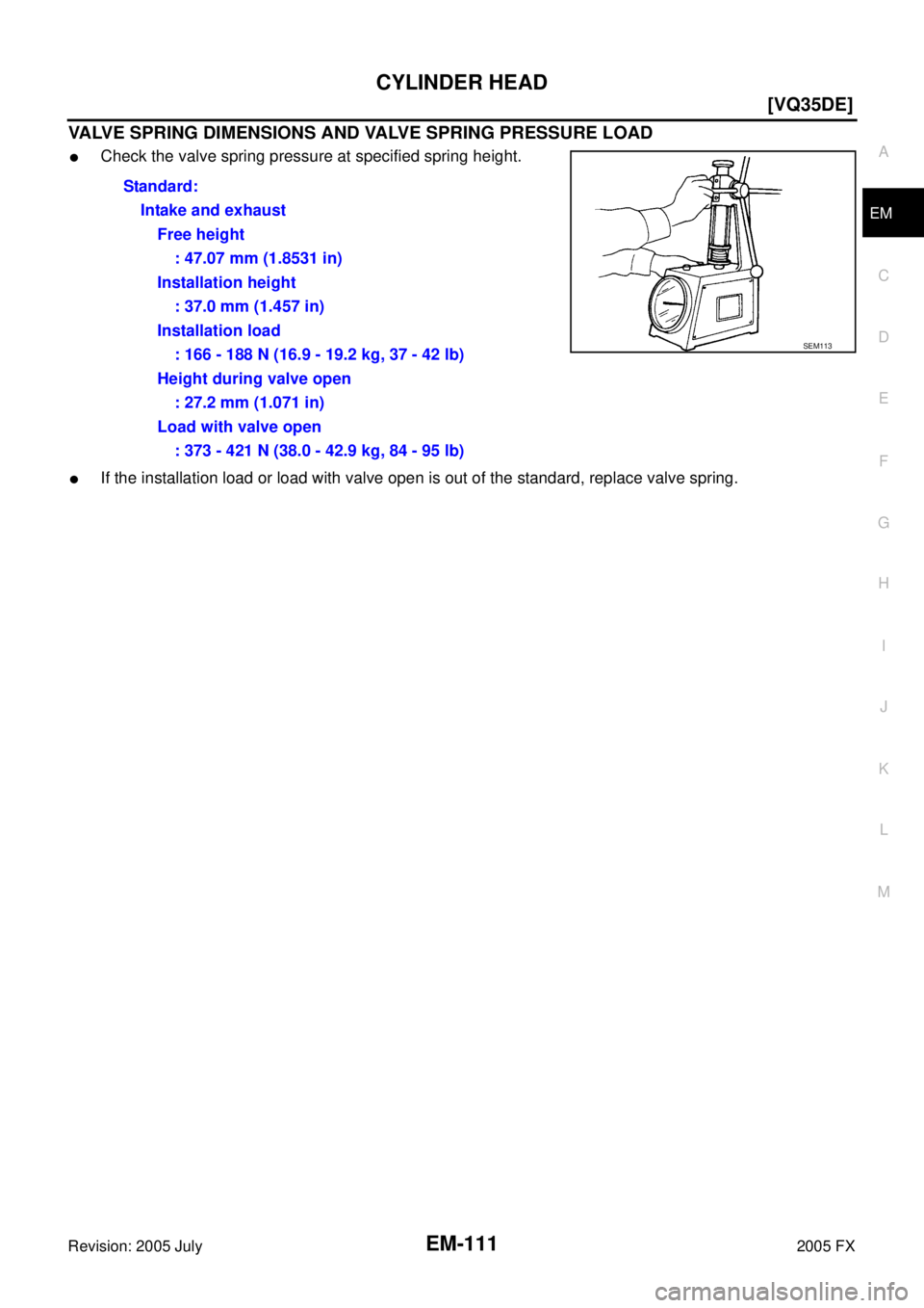
VALVE SPRING DIMENSIONS AND VALVE SPRING PRESSURE LOAD
�Check the valve spring pressure at specified spring height.
�If the installation load or load with valve open is out of the standard, replace valve spring. Standard:
Intake and exhaustFree height : 47.07 mm (1.8531 in)
Installation height : 37.0 mm (1.457 in)
Installation load : 166 - 188 N (16.9 - 19.2 kg, 37 - 42 lb)
Height during valve open : 27.2 mm (1.071 in)
Load with valve open : 373 - 421 N (38.0 - 42.9 kg, 84 - 95 lb)
SEM113
Page 2983 of 4731
![INFINITI FX35 2005 Service Manual EM-148
[VQ35DE]
CYLINDER BLOCK
Revision: 2005 July 2005 FX
�Remove main bearing caps and bearings, and using the scale
on the plastigage bag, measure the plastigage width.
NOTE:
The procedure when](/manual-img/42/57020/w960_57020-2982.png "INFINITI FX35 2005 Service Manual EM-148
[VQ35DE]
CYLINDER BLOCK
Revision: 2005 July 2005 FX
�Remove main bearing caps and bearings, and using the scale
on the plastigage bag, measure the plastigage width.
NOTE:
The procedure when")
EM-148
[VQ35DE]
CYLINDER BLOCK
Revision: 2005 July 2005 FX
�Remove main bearing caps and bearings, and using the scale
on the plastigage bag, measure the plastigage width.
NOTE:
The procedure when the measured value exceeds the limit is
same as that described in the “Method by Calculation”.
MAIN BEARING CRUSH HEIGHT
�When main bearing cap is removed after being tightened to the
specified torque with main bearings installed, the tip end of bear-
ing must protrude. Refer to EM-128, "
ASSEMBLY" for the tight-
ening procedure.
�If the standard is not met, replace main bearings.
CONNECTING ROD BEARING CRUSH HEIGHT
�When connecting rod bearing cap is removed after being tight-
ened to the specified torque with connecting rod bearings
installed, the tip end of bearing must protrude. Refer to EM-128,
"ASSEMBLY" for the tightening procedure.
�If the standard is not met, replace connecting rod bearings.
MAIN BEARING CAP BOLT OUTER DIAMETER
�Measure the outer diameters (“d1 ”, “d2 ”) at two positions as
shown in the figure.
�If reduction appears in “A” range, regard it as “d2 ”.
�If it exceeds the limit (large difference in dimensions), replace
main bearing cap bolt with new one.
PBIC1149E
Standard : There must be crush height.
SEM502G
Standard : There must be crush height.
PBIC1646E
Limit (“d1 ” – “d2
”) : 0.11 mm (0.0043 in)
PBIC0911E
Page 2987 of 4731
![INFINITI FX35 2005 Service Manual EM-152
[VQ35DE]
SERVICE DATA AND SPECIFICATIONS (SDS)
Revision: 2005 July 2005 FX
CAMSHAFT AND CAMSHAFT BEARING
Unit: mm (in)
*
1 : Cam wear limit
*2 : Total indicator reading
Valve Lifter
Unit: mm](/manual-img/42/57020/w960_57020-2986.png "INFINITI FX35 2005 Service Manual EM-152
[VQ35DE]
SERVICE DATA AND SPECIFICATIONS (SDS)
Revision: 2005 July 2005 FX
CAMSHAFT AND CAMSHAFT BEARING
Unit: mm (in)
*
1 : Cam wear limit
*2 : Total indicator reading
Valve Lifter
Unit: mm")
EM-152
[VQ35DE]
SERVICE DATA AND SPECIFICATIONS (SDS)
Revision: 2005 July 2005 FX
CAMSHAFT AND CAMSHAFT BEARING
Unit: mm (in)
*
1 : Cam wear limit
*2 : Total indicator reading
Valve Lifter
Unit: mm (in)
Valve Clearance
Unit: mm (in)
*: Approximately 80 °C (176 °F)
Items
Standard Limit
Camshaft journal oil clearance No. 1 0.045 - 0.086 (0.0018 - 0.0034)
0.15 (0.0059)
No. 2, 3, 4 0.035 - 0.076 (0.0014 - 0.0030)
Camshaft bracket inner diameter No. 1 26.000 - 26.021 (1.0236 - 1.0244) —
No. 2, 3, 4 23.500 - 23.521 (0.9252 - 0.9260) —
Camshaft journal diameter No. 1 25.935 - 25.955 (1.0211 - 1.0218) —
No. 2, 3, 4 23.445 - 23.465 (0.9230 - 0.9238) —
Camshaft end play 0.115 - 0.188 (0.0045 - 0.0074) 0.24 (0.0094)
Camshaft cam height “A” Intake and exhaust 44.865 - 45.055 (1.7663 - 1.7738) 0.2 (0.008)*
1
Camshaft runout [TIR*2 ] Less than 0.02 mm (0.0008) 0.05 (0.0020)
Camshaft sprocket runout [TIR*
2 ] — 0.15 (0.0059)
SEM671
Items
Standard
Valve lifter outer diameter 33.977 - 33.987 (1.3377 - 1.3381)
Valve lifter hole diameter 34.000 - 34.016 (1.3386 - 1.3392)
Valve lifter clearance 0.013 - 0.039 (0.0005 - 0.0015)
Items Cold Hot* (reference data)
Intake 0.26 - 0.34 (0.010 - 0.013) 0.304 - 0.416 (0.012 - 0.016)
Exhaust 0.29 - 0.37 (0.011 - 0.015) 0.308 - 0.432 (0.012 - 0.017)
Page 2989 of 4731
EM-154
[VQ35DE]
SERVICE DATA AND SPECIFICATIONS (SDS)
Revision: 2005 July 2005 FX
CYLINDER HEAD
Unit: mm (in)
Valve Dimensions
Unit: mm (in)
Items Standard Limit
Head surface distortion Less than 0.03 (0.0012) 0.1 (0.004)
Normal cylinder head height “H” 126.3 - 126.5 (4.97 - 4.98) —
PBIC0924E
Valve head diameter “D” Intake 37.0 - 37.3 (1.457 - 1.469) Exhaust 31.2 - 31.5 (1.228 - 1.240)
Valve length “L” Intake 96.46 (3.7976)
Exhaust 93.99 (3.7004)
Valve stem diameter “d” Intake 5.965 - 5.980 (0.2348 - 0.2354)
Exhaust 5.955 - 5.970 (0.2344 - 0.2350)
Valve seat angle “ α” Intake
45 °15 ′ - 45 °45 ′
Exhaust
Valve margin “T” Intake 1.1 (0.043)
Exhaust 1.3 (0.051)
Valve margin “T” limit 0.5 (0.020)
Valve stem end surface grinding limit 0.2 (0.008)
SEM188
Page 2991 of 4731
![INFINITI FX35 2005 Service Manual EM-156
[VQ35DE]
SERVICE DATA AND SPECIFICATIONS (SDS)
Revision: 2005 July 2005 FX
Valve Seat
Unit: mm (in)
*
1 : Diameter made by intersection point of conic angles “ α1” and “ α2”
*2 :](/manual-img/42/57020/w960_57020-2990.png "INFINITI FX35 2005 Service Manual EM-156
[VQ35DE]
SERVICE DATA AND SPECIFICATIONS (SDS)
Revision: 2005 July 2005 FX
Valve Seat
Unit: mm (in)
*
1 : Diameter made by intersection point of conic angles “ α1” and “ α2”
*2 :")
EM-156
[VQ35DE]
SERVICE DATA AND SPECIFICATIONS (SDS)
Revision: 2005 July 2005 FX
Valve Seat
Unit: mm (in)
*
1 : Diameter made by intersection point of conic angles “ α1” and “ α2”
*2 : Diameter made by intersection point of conic angles “ α2” and “ α3”
*3 : Machining data
Valve Spring
Items Standard Oversize [0.5 (0.02)] (Service)
Cylinder head seat recess diameter “D” Intake 38.000 - 38.016 (1.4961 - 1.4967) 38.500 - 38.516 (1.5157 - 1.5164)
Exhaust 32.200 - 32.216 (1.2677 - 1.2683) 32.700 - 32.716 (1.2874 - 1.2880)
Valve seat outer diameter “d” Intake 38.097 - 38.113 (1.4999 - 1.5005) 38.597 - 38.613 (1.5196 - 1.5202)
Exhaust 32.280 - 32.296 (1.2709 - 1.2715) 32.780 - 32.796 (1.2905 - 1.2912)
Valve seat interference fit Intake 0.081 - 0.113 (0.0032 - 0.0044)
Exhaust 0.064 - 0.096 (0.0025 - 0.0038)
Diameter “d1”*
1Intake 35 (1.38)
Exhaust 28.7 (1.130)
Diameter “d2”*
2Intake 36.6 - 36.8 (1.441 - 1.449)
Exhaust 30.6 - 30.8 (1.205 - 1.213)
Angle “ α1” Intake 60
°
Exhaust 60 °
Angle “ α2” Intake 88
°45 ′ - 90 °15 ′
Exhaust 88 °45 ′ - 90 °15 ′
Angle “ α3” Intake 120
°
Exhaust 120 °
Contacting width “W”*
3Intake 1.09 - 1.31 (0.0429 - 0.0516)
Exhaust 1.29 - 1.51 (0.0508 - 0.0594)
Height “h” Intake 5.9 - 6.0 (0.232 - 0.236) 5.05 - 5.15 (0.1988 - 0.2028)
Exhaust 5.9 - 6.0 (0.232 - 0.236) 4.95 - 5.05 (0.1949 - 0.1988)
Depth “H” 6.0 (0.236)
PBIC2745E
Free height mm (in) 47.07 (1.8531)
Pressure N (kg, lb) at height mm (in) Installation 166 - 188 (16.9 - 19.2, 37 - 42) at 37.0 (1.457)
Valve open 373 - 421 (38.0 - 42.9, 84 - 95) at 27.2 (1.071)
Out-of-square mm (in) Limit 2.1 (0.083)
Page 3018 of 4731
![INFINITI FX35 2005 Service Manual EXHAUST MANIFOLD AND THREE WAY CATALYST EM-183
[VK45DE]
C
D E
F
G H
I
J
K L
M A
EM
Revision: 2005 July 2005 FX
b. Remove heated oxygen sensor 1 and 2 on both bank with
heated oxygen sens](/manual-img/42/57020/w960_57020-3017.png "INFINITI FX35 2005 Service Manual EXHAUST MANIFOLD AND THREE WAY CATALYST EM-183
[VK45DE]
C
D E
F
G H
I
J
K L
M A
EM
Revision: 2005 July 2005 FX
b. Remove heated oxygen sensor 1 and 2 on both bank with
heated oxygen sens")
EXHAUST MANIFOLD AND THREE WAY CATALYST EM-183
[VK45DE]
C
D E
F
G H
I
J
K L
M A
EM
Revision: 2005 July 2005 FX
b. Remove heated oxygen sensor 1 and 2 on both bank with
heated oxygen sensor wrench (SST).
�Put marks to identify installation positions of each heated oxy-
gen sensor.
CAUTION:
�Be careful not to damage heated oxygen sensor.
�Discard any heated oxygen sensor which has been
dropped from a height of more than 0.5 m (19.7 in) onto a
hard surface such as a concrete floor; replace with a new
one.
9. Remove exhaust mounting bracket between three way catalysts (right and left bank) and transmission. Refer to EX-3, "
EXHAUST SYSTEM" .
10. Disconnect A/C piping from A/C compressor, then remove A/C compressor with power tool. Refer to AT C -
140, "Components" .
11. Remove alternator and bracket. Refer to SC-23, "
CHARGING SYSTEM" .
12. Remove exhaust front tube with power tool. Refer to EX-3, "
EXHAUST SYSTEM" .
13. Remove steering lower joint at power steering gear assembly side, and release steering lower shaft. Refer to PS-19, "
POWER STEERING GEAR AND LINKAGE" .
14. Remove three way catalysts (right and left bank).
15. Remove exhaust manifold covers. (right and left bank)
16. Loosen mounting nuts in reverse order as shown in the figure to remove exhaust manifold.
NOTE:
Disregard the numerical order No. 9 to 12 in removal.
17. Remove exhaust manifold gaskets. CAUTION:
Cover engine openings to avoid entry of foreign materials.
PBIC2333E
PBIC2334E
PBIC1549E
Page 3043 of 4731
![INFINITI FX35 2005 Service Manual EM-208
[VK45DE]
TIMING CHAIN
Revision: 2005 July 2005 FX
7. Install oil pump drive spacer as follows:
a. Insert oil pump drive spacer according to the directions of crank- shaft key and the two flat](/manual-img/42/57020/w960_57020-3042.png "INFINITI FX35 2005 Service Manual EM-208
[VK45DE]
TIMING CHAIN
Revision: 2005 July 2005 FX
7. Install oil pump drive spacer as follows:
a. Insert oil pump drive spacer according to the directions of crank- shaft key and the two flat")
EM-208
[VK45DE]
TIMING CHAIN
Revision: 2005 July 2005 FX
7. Install oil pump drive spacer as follows:
a. Insert oil pump drive spacer according to the directions of crank- shaft key and the two flat surfaces of oil pump inner rotor.
�If the positional relationship does not allow the insertion,
rotate oil pump inner rotor with a finger to allow spacer.
b. After confirming that the position of each part is in correct condi- tion to allow for spacer, force fit spacer by lightly tapping with
plastic hammer until it contacts and does not go further.
8. Install front oil seal on front cover.
�Apply new engine oil to both oil seal lip and dust seal lip.
�Install it so that each seal lip is oriented as shown in the fig-
ure.
CAUTION:
Be careful not to scratch or make burrs on circumference
of oil seal.
�Using front oil seal drift (commercial service tool), press fit
until the height of front oil seal is level with the mounting sur-
face.
�Make sure the garter spring is in position and seal lips not
inverted.
9. Install chain tensioner cover to front cover.
�Apply a continuous bead of liquid gasket with tube presser
[SST: WS39930000 ( — )] to front cover as shown in the
figure.
Use Genuine RTV Silicone Sealant or equivalent. Refer to
GI-48, "
RECOMMENDED CHEMICAL PRODUCTS AND
SEALANTS" .
10. Install front cover as follows:
PBIC0058E
SEM715A
Front oil seal drift Outer diameter : 56 mm (2.20 in)
Inner diameter : 49 mm (1.93 in)
PBIC0059E
SBIA0372E
![INFINITI FX35 2005 Service Manual EM-154
[VQ35DE]
SERVICE DATA AND SPECIFICATIONS (SDS)
Revision: 2005 July 2005 FX
CYLINDER HEAD
Unit: mm (in)
Valve Dimensions
Unit: mm (in)
Items Standard Limit
Head surface distortion Less than 0.](/manual-img/42/57020/w960_57020-2988.png "INFINITI FX35 2005 Service Manual EM-154
[VQ35DE]
SERVICE DATA AND SPECIFICATIONS (SDS)
Revision: 2005 July 2005 FX
CYLINDER HEAD
Unit: mm (in)
Valve Dimensions
Unit: mm (in)
Items Standard Limit
Head surface distortion Less than 0.")