Page 4616 of 4731

TROUBLE DIAGNOSIS SRS-33
C
D E
F
G
I
J
K L
M A
B
SRS
Revision: 2005 July 2005 FX
Trouble Diagnosis: “AIR BAG” Warning Lamp Does Not Turn OFFAHS000HU
DIAGNOSTIC PROCEDURE 7
1. CHECK THE DEPLOYMENT OF AIR BAG MODULE
Is air bag module deployed?
YES or NO
YES >> Refer to SRS-46, "COLLISION DIAGNOSIS" .
NO >> GO TO 2.
2. CHECK THE AIR BAG FUSE
Check 10A fuse [No. 13, located in fuse block (J/B)].
Refer to PG-3, "
POWER SUPPLY ROUTING CIRCUIT" .
OK or NG
OK >> GO TO 4.
NG >> GO TO 3.
3. CHECK AIR BAG FUSE AGAIN
Replace “AIR BAG” fuse and turn ignition switch ON.
Does the
“AIR BAG” fuse blow again?
YES >> Repair or replace main harness.
NO >> INSPECTION END
4. CHECK DIAGNOSIS SENSOR UNIT
Connect CONSULT-II and touch “START”.
�Is “AIR BAG” displayed on CONSULT-II?
YES or NO
YES >> GO TO 5.
NO >> Visually check the wiring harness connection of diagno- sis sensor unit. If the harness connection check result is
OK, replace diagnosis sensor unit.
5. CHECK HARNESS CONNECTION
Is harness connection between warning lamp and diagnosis sensor unit OK?
OK or NG
OK >> Replace diagnosis sensor unit.
NG >> Connect “AIR BAG” warning lamp and diagnosis sensor unit connector properly. If “AIR BAG” warning lamp still does not go off, replace harness.
BCIA0030E
Page 4617 of 4731
SRS-34
TROUBLE DIAGNOSIS
Revision: 2005 July 2005 FX
Trouble Diagnosis: “AIR BAG” Warning Lamp Does Not Turn ONAHS000HV
DIAGNOSTIC PROCEDURE 8
1. CHECK METER FUSE
Check 10A fuse [No. 14, located in fuse block (J/B)].
Refer to PG-3, "
POWER SUPPLY ROUTING CIRCUIT" .
OK or NG
OK >> GO TO 3.
NG >> GO TO 2.
2. CHECK METER FUSE AGAIN
Replace 10A fuse [No. 14, located in fuse block (J/B)] and turn ignition switch ON.
Does the meter fuse blow again?
YES >> Repair or replace the related harness.
NO >> INSPECTION END
3. CHECK HARNESS CONNECTION BETWEEN DIAGNOSIS SENSOR UNIT AND COMBINATION
METER
Disconnect diagnosis sensor unit connector and turn ignition switch ON.
�Does “AIR BAG” warning lamp turn on?
YES or NO
YES >> Replace diagnosis sensor unit.
NO >> Replace combination meter assembly.
Page 4618 of 4731
DRIVER AIR BAG MODULE SRS-35
C
D E
F
G
I
J
K L
M A
B
SRS
Revision: 2005 July 2005 FX
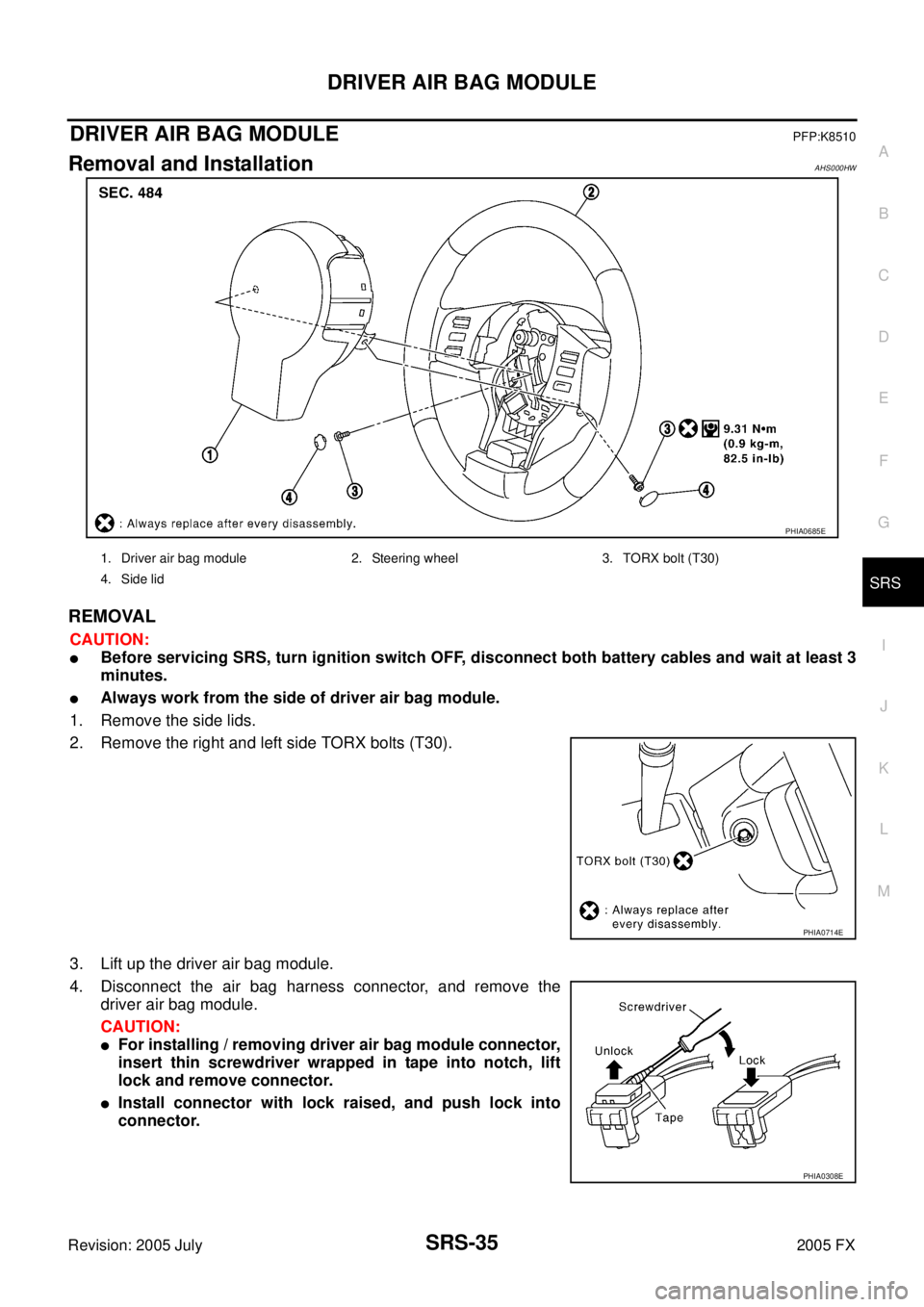
DRIVER AIR BAG MODULEPFP:K8510
Removal and InstallationAHS000HW
REMOVAL
CAUTION:
�Before servicing SRS, turn ignition switch OFF, disconnect both battery cables and wait at least 3
minutes.
�Always work from the side of driver air bag module.
1. Remove the side lids.
2. Remove the right and left side TORX bolts (T30).
3. Lift up the driver air bag module.
4. Disconnect the air bag harness connector, and remove the driver air bag module.
CAUTION:
�For installing / removing driver air bag module connector,
insert thin screwdriver wrapped in tape into notch, lift
lock and remove connector.
�Install connector with lock raised, and push lock into
connector.
PHIA0685E
1. Driver air bag module 2. Steering wheel 3. TORX bolt (T30)
4. Side lid
PHIA0714E
PHIA0308E
Page 4621 of 4731
SRS-38
SPIRAL CABLE
Revision: 2005 July 2005 FX
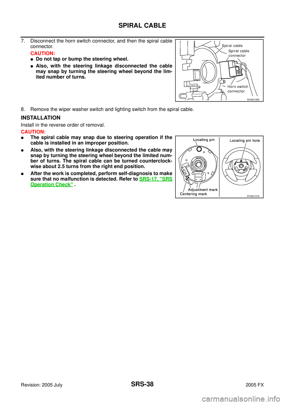
7. Disconnect the horn switch connector, and then the spiral cable
connector.
CAUTION:
�Do not tap or bump the steering wheel.
�Also, with the steering linkage disconnected the cable
may snap by turning the steering wheel beyond the lim-
ited number of turns.
8. Remove the wiper washer switch and lighting switch from the spiral cable.
INSTALLATION
Install in the reverse order of removal.
CAUTION:
�The spiral cable may snap due to steering operation if the
cable is installed in an improper position.
�Also, with the steering linkage disconnected the cable may
snap by turning the steering wheel beyond the limited num-
ber of turns. The spiral cable can be turned counterclock-
wise about 2.5 turns from the right end position.
�After the work is completed, perform self-diagnosis to make
sure that no malfunction is detected. Refer to SRS-17, "
SRS
Operation Check" .
SHIA0193E
PHIA0101E
Page 4640 of 4731
PREPARATION TF-7
C E F
G H
I
J
K L
M A
B
TF
Revision: 2005 July 2005 FX
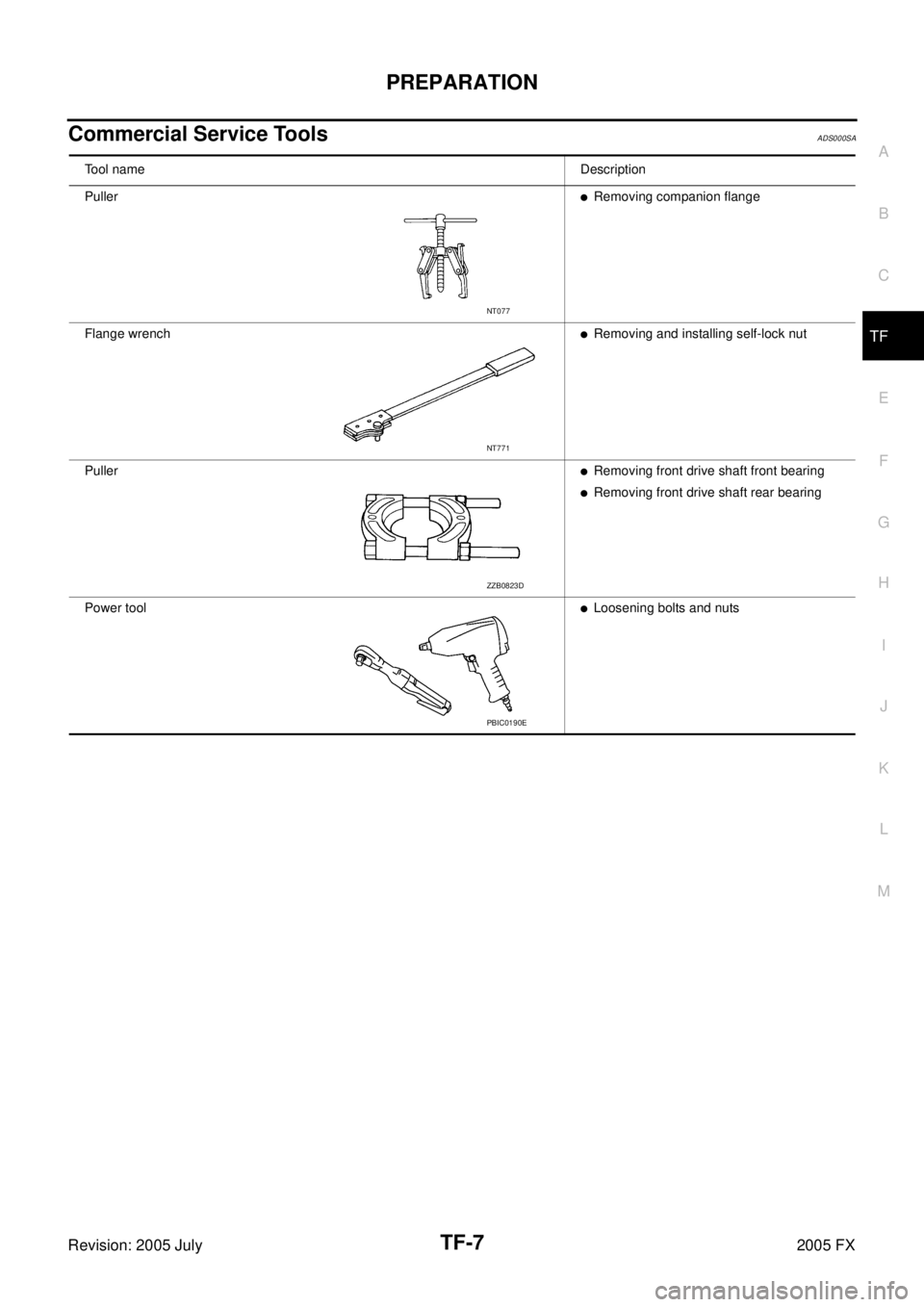
Commercial Service ToolsADS000SA
Tool nameDescription
Puller
�Removing companion flange
Flange wrench
�Removing and installing self-lock nut
Puller
�Removing front drive shaft front bearing
�Removing front drive shaft rear bearing
Power tool
�Loosening bolts and nuts
NT077
NT771
ZZB0823D
PBIC0190E
Page 4657 of 4731

TF-24
TROUBLE DIAGNOSIS
Revision: 2005 July 2005 FX
DATA MONITOR MODE
Operation Procedure
1. Perform “CONSULT-II SETTING PROCEDURE”. Refer to TF-22, "CONSULT-II SETTING PROCEDURE"
.
2. Touch “DATA MONITOR”.
3. Select from “SELECT MONITOR ITEM”, screen of data monitor mode is displayed. NOTE:
When malfunction is detected, CONSULT-II performs REAL-TIME DIAGNOSIS.
Also, any malfunction detected while in this mode will be displayed at real time.
Display Item List
× : Standard –: Not applicable
Monitored item (Unit) Monitor item selection
Remarks
ECU INPUT
SIGNALS MAIN
SIGNALS SELECTION
FROM MENU
FR RH SENSOR [km/h] or [mph] ××× Wheel speed calculated by front wheel
sensor RH signal is displayed.
FR LH SENSOR [km/h] or [mph] ××× Wheel speed calculated by front wheel
sensor LH signal is displayed.
RR RH SENSOR [km/h] or [mph] ××× Wheel speed calculated by rear wheel
sensor RH signal is displayed.
RR LH SENSOR [km/h] or [mph] ××× Wheel speed calculated by rear wheel
sensor LH signal is displayed.
BATTERY VOLT [V] – – ×Power supply voltage for AWD control unit
THRTL POS SEN [%] – – ×Throttle opening status is displayed.
ETS SOLENOID [A] – – × Monitored value of current at AWD sole-
noid
STOP LAMP SW [ON/OFF] – – × Stop lamp switch signal status via CAN
communication line is displayed.
ENG SPEED SIG [RUN/STOP] – – ×Engine status is displayed.
ETS ACTUATOR [ON/OFF] – – × Operating condition of AWD actuator relay
(integrated in AWD control unit) is dis-
played.
4WD WARN LAMP [ON/OFF] – – × Control status of AWD warning lamp is dis-
played.
4WD MODE SW [AUTO] – – × AWD lock switch is not equipped, but dis-
played.
4WD MODE MON [AUTO] – – ×Control status of AWD is displayed.
DIS-TIRE MONI [mm] – – × Improper size tire installed condition is dis-
played.
P BRAKE SW [ON/OFF] – – × Parking switch signal status via CAN com-
munication line is displayed.
Voltage [V] – – × The value measured by the voltage probe
is displayed.
Frequency [Hz] – – ×
The value measured by the pulse probe is
displayed.
DUTY-HI (high) [%] – –
×
DUTY-LOW (low) [%] – – ×
PLS WIDTH-HI [msec] – – ×
PLS WIDTH-LOW [msec] – – ×
Page 4659 of 4731

TF-26
TROUBLE DIAGNOSIS FOR SYSTEM
Revision: 2005 July 2005 FX
TROUBLE DIAGNOSIS FOR SYSTEMPFP:00000
Power Supply Circuit for AWD Control UnitADS000SX
CONSULT-II REFERENCE VALUE IN DATA MONITOR MODE
Data are reference value.
DIAGNOSTIC PROCEDURE
1. CHECK POWER SUPPLY
1. Turn ignition switch “OFF”.
2. Disconnect AWD control unit harness connector.
3. Turn ignition switch “ON”. (Do not start engine.)
4. Check voltage between AWD control unit harness connector ter- minals and ground.
5. Turn ignition switch “OFF”.
6. Check voltage between AWD control unit harness connector ter- minals and ground.
OK or NG
OK >> GO TO 2.
NG >> Check the following. If any items are damaged, repair or replace damaged parts.
�10A fuse [No. 12 or 21, located in the fuse block (J/B)]
�Harness for short or open between battery and AWD control unit harness connector terminal 9
�Harness for short or open between ignition switch and AWD control unit harness connector ter-
minal 7
�Ignition switch. Refer to PG-3, "POWER SUPPLY ROUTING CIRCUIT" .
Monitored item [Unit] Condition Display value (Approx.)
BATTERY VOLT [V] Ignition switch: ON Battery voltage
Connector Terminal (Wire color) Voltage (Approx.)
M92 7 (G/R) - Ground
Battery voltage
9 (G/W) - Ground
SDIA2319E
Connector Terminal (Wire color) Voltage (Approx.)
M92 7 (G/R) - Ground 0V
9 (G/W) - Ground Battery voltage
SDIA2320E
Page 4662 of 4731

TROUBLE DIAGNOSIS FOR SYSTEM TF-29
C E F
G H
I
J
K L
M A
B
TF
Revision: 2005 July 2005 FX
1. CHECK AWD SOLENOID SIGNAL
With CONSULT-II
1. Start engine.
2. Select “DATA MONITOR” mode for “ALL MODE AWD/4WD” with CONSULT-II.
3. Read out the value of “ETS SOLENOID”.
*: The values are changed by throttle opening and engine speed.
OK or NG
OK >> GO TO 6.
NG >> GO TO 2.
2. CHECK POWER SUPPLY
1. Turn ignition switch “OFF”.
2. Disconnect AWD control unit harness connector.
3. Turn ignition switch “ON”. (Do not start engine.)
4. Check voltage between AWD control unit harness connector ter- minal 9 and ground.
OK or NG
OK >> GO TO 3.
NG >> Check the following. If any items are damaged, repair or replace damaged parts.
�10A fuse [No. 21, located in the fuse block (J/B)]
�Harness for short or open between battery and AWD
control unit harness connector terminal 9
3. CHECK AWD SOLENOID CIRCUIT
1. Turn ignition switch “OFF”.
2. Disconnect AWD control unit harness connector.
3. Check resistance between AWD control unit harness connector terminals 1 and 2.
OK or NG
OK >> GO TO 6.
NG >> GO TO 4.
Condition Display value
Engine running At idle speed Approx. 0.000A
When depressing accelerator
pedal Approx. 0.000 - 2.400A*
SDIA1885E
Connector Terminal (Wire color) Voltage (Approx.)
M92 9 (G/W) - Ground Battery voltage
SDIA1884E
Connector Terminal (Wire color) Resistance (Approx.)M92 1 (L/W) - 2 (L/OR) (Ground) 2.45 Ω
SDIA1928E