Page 4557 of 4731

SE-84
AUTOMATIC DRIVE POSITIONER
Revision: 2005 July 2005 FX
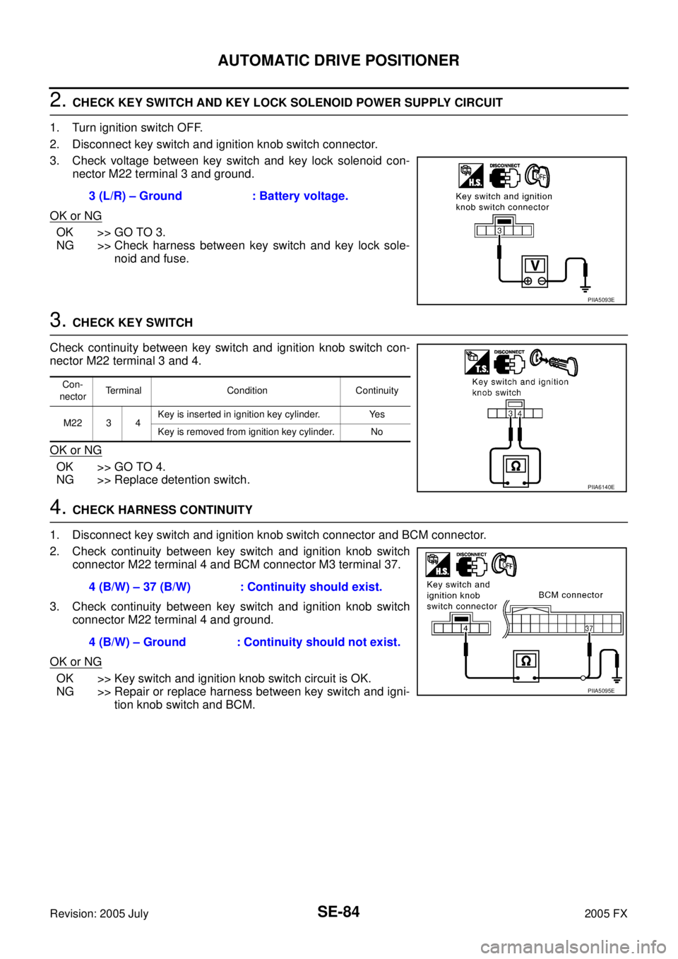
2. CHECK KEY SWITCH AND KEY LOCK SOLENOID POWER SUPPLY CIRCUIT
1. Turn ignition switch OFF.
2. Disconnect key switch and ignition knob switch connector.
3. Check voltage between key switch and key lock solenoid con- nector M22 terminal 3 and ground.
OK or NG
OK >> GO TO 3.
NG >> Check harness between key switch and key lock sole- noid and fuse.
3. CHECK KEY SWITCH
Check continuity between key switch and ignition knob switch con-
nector M22 terminal 3 and 4.
OK or NG
OK >> GO TO 4.
NG >> Replace detention switch.
4. CHECK HARNESS CONTINUITY
1. Disconnect key switch and ignition knob switch connector and BCM connector.
2. Check continuity between key switch and ignition knob switch connector M22 terminal 4 and BCM connector M3 terminal 37.
3. Check continuity between key switch and ignition knob switch connector M22 terminal 4 and ground.
OK or NG
OK >> Key switch and ignition knob switch circuit is OK.
NG >> Repair or replace harness between key switch and igni- tion knob switch and BCM.
3 (L/R) – Ground : Battery voltage.
PIIA5093E
Con-
nector Terminal Condition Continuity
M22 3 4 Key is inserted in ignition key cylinder. Yes
Key is removed from ignition key cylinder. No
PIIA6140E
4 (B/W) – 37 (B/W) : Continuity should exist.
4 (B/W) – Ground : Continuity should not exist.
PIIA5095E
Page 4558 of 4731

AUTOMATIC DRIVE POSITIONER SE-85
C
D E
F
G H
J
K L
M A
B
SE
Revision: 2005 July 2005 FX
Key Switch Circuit Check (Without Intelligent Key)AIS003G1
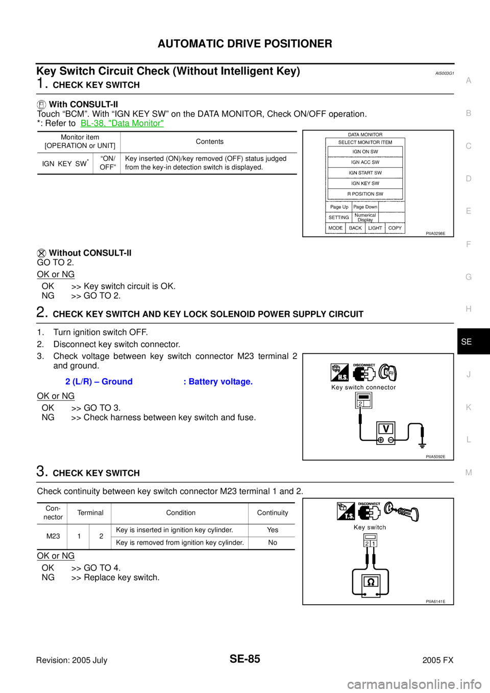
1. CHECK KEY SWITCH
With CONSULT-II
Touch “BCM”. With “IGN KEY SW” on the DATA MONITOR, Check ON/OFF operation.
*: Refer to BL-38, "
Data Monitor"
Without CONSULT-II
GO TO 2.
OK or NG
OK >> Key switch circuit is OK.
NG >> GO TO 2.
2. CHECK KEY SWITCH AND KEY LOCK SOLENOID POWER SUPPLY CIRCUIT
1. Turn ignition switch OFF.
2. Disconnect key switch connector.
3. Check voltage between key switch connector M23 terminal 2 and ground.
OK or NG
OK >> GO TO 3.
NG >> Check harness between key switch and fuse.
3. CHECK KEY SWITCH
Check continuity between key switch connector M23 terminal 1 and 2.
OK or NG
OK >> GO TO 4.
NG >> Replace key switch.
Monitor item
[OPERATION or UNIT] Contents
IGN KEY SW
*“ON/
OFF” Key inserted (ON)/key removed (OFF) status judged
from the key-in detection switch is displayed.
PIIA0298E
2 (L/R) – Ground : Battery voltage.
PIIA5092E
Con-
nector Terminal Condition Continuity
M23 1 2 Key is inserted in ignition key cylinder. Yes
Key is removed from ignition key cylinder. No
PIIA6141E
Page 4561 of 4731

SE-88
AUTOMATIC DRIVE POSITIONER
Revision: 2005 July 2005 FX
Memory Indicator Lamp Circuit CheckAIS002Y7
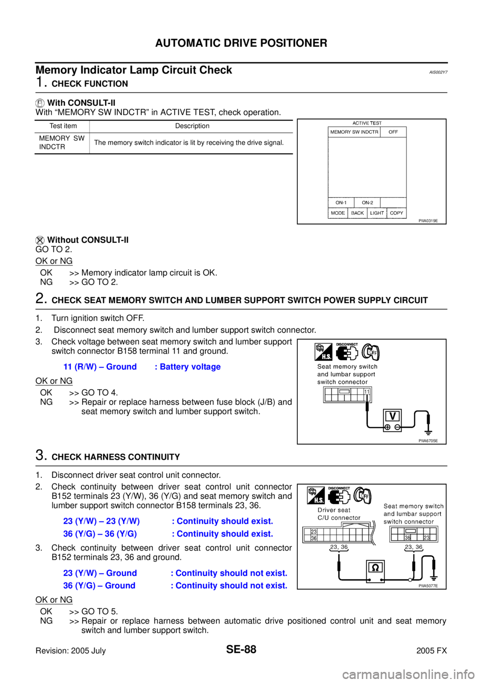
1. CHECK FUNCTION
With CONSULT-II
With “MEMORY SW INDCTR” in ACTIVE TEST, check operation.
Without CONSULT-II
GO TO 2.
OK or NG
OK >> Memory indicator lamp circuit is OK.
NG >> GO TO 2.
2. CHECK SEAT MEMORY SWITCH AND LUMBER SUPPORT SWITCH POWER SUPPLY CIRCUIT
1. Turn ignition switch OFF.
2. Disconnect seat memory switch and lumber support switch connector.
3. Check voltage between seat memory switch and lumber support switch connector B158 terminal 11 and ground.
OK or NG
OK >> GO TO 4.
NG >> Repair or replace harness between fuse block (J/B) and
seat memory switch and lumber support switch.
3. CHECK HARNESS CONTINUITY
1. Disconnect driver seat control unit connector.
2. Check continuity between driver seat control unit connector B152 terminals 23 (Y/W), 36 (Y/G) and seat memory switch and
lumber support switch connector B158 terminals 23, 36.
3. Check continuity between driver seat control unit connector B152 terminals 23, 36 and ground.
OK or NG
OK >> GO TO 5.
NG >> Repair or replace harness between automatic drive positioned control unit and seat memory
switch and lumber support switch.
Test item Description
MEMORY SW
INDCTR The memory switch indicator is lit by receiving the drive signal.
PIIA0319E
11 (R/W) – Ground : Battery voltage
PIIA6705E
23 (Y/W) – 23 (Y/W) : Continuity should exist.
36 (Y/G) – 36 (Y/G) : Continuity should exist.
23 (Y/W) – Ground : Continuity should not exist.
36 (Y/G) – Ground : Continuity should not exist.
PIIA5077E
Page 4563 of 4731

SE-90
AUTOMATIC DRIVE POSITIONER
Revision: 2005 July 2005 FX
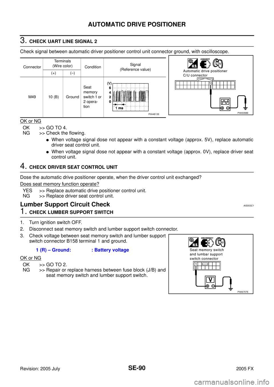
3. CHECK UART LINE SIGNAL 2
Check signal between automatic driver positioner control unit connector ground, with oscilloscope.
OK or NG
OK >> GO TO 4.
NG >> Check the flowing.
�When voltage signal dose not appear with a constant voltage (approx. 5V), replace automatic
driver seat control unit.
�When voltage signal dose not appear with a constant voltage (approx. 0V), replace driver seat
control unit.
4. CHECK DRIVER SEAT CONTROL UNIT
Dose the automatic drive positioner operate, when the driver control unit exchanged?
Does seat memory function operate?
YES >> Replace automatic drive positioner control unit.
NG >> Replace driver seat control unit.
Lumber Support Circuit CheckAIS003C1
1. CHECK LUMBER SUPPORT SWITCH
1. Turn ignition switch OFF.
2. Disconnect seat memory switch and lumber support switch connector.
3. Check voltage between seat memory switch and lumber support switch connector B158 terminal 1 and ground.
OK or NG
OK >> GO TO 2.
NG >> Repair or replace harness between fuse block (J/B) and
seat memory switch and lumber support switch.
Connector Te r m i n a l s
(Wire color) Condition Signal
(Reference value)
(+) (–)
M49 10 (B) Ground Seat
memory
switch 1 or
2 opera-
tion
PIIA5098EPIIA4813E
1 (R) – Ground: : Battery voltage
PIIA6707E
Page 4569 of 4731
SE-96
POWER SEAT
Revision: 2005 July 2005 FX
Trouble DiagnosisAIS003L4
A trouble diagnosis of a automatic drive positioner interlocking power seat is refer to SE-11, "AUTOMATIC
DRIVE POSITIONER" .
Page 4574 of 4731
FRONT SEAT SE-101
C
D E
F
G H
J
K L
M A
B
SE
Revision: 2005 July 2005 FX
1. Headrest 2. Headrest holder (free) 3. Headrest holder (locked)
4. Seatback pad 5. Seatback trim 6. Seat cushion inner finisher
7. Screw 8. Power seat switch assembly 9. Seat cushion trim
10. Seat cushion pad 11. Seatback garnish 12. Nut
13. Side air bag module 14. Clip (C101) 15. Inner cloth stay
16. Lumber support device 17. Bolt 18. Seatback frame
19. Reclining device assembly 20. Seat cushion frame 21. Seat harness assembly
22. Seat adjust assembly 23. Clip (C103) 24. Seat adjust assembly cover
25. Seat cushion outer finisher 26. Seat cushion outer finisher cover 27. Power seat memory switch assembly
28. Seat cushion forward finisher 29. Seat cushion forward finisher lid
Page 4580 of 4731
REAR SEAT SE-107
C
D E
F
G H
J
K L
M A
B
SE
Revision: 2005 July 2005 FX
1. Headrest (side) 2. Headrest holder (free) 3. Headrest holder (locked)
4. Seatback trim (RH) 5. Seatback pad (RH) 6. Seatback frame (RH)
7. Nut 8. Seat hinge cover (RH) 9. Screw
10. Reclining lever (RH) 11. Reclining device outer cover (RH) 12. Reclining device inner cover (RH)
13. Bolt 14. Seatback garnish (RH) 15. Trunk net hook
16. Clip (C101) 17. Headrest (center) 18. Seatback trim (LH)
19. Seatback pad (LH) 20. Seatback frame (LH) 21. Seatback garnish (LH)
22. Armrest bracket cover 23. Armrest bracket 24. Armrest
25. Reclining device inner cover (LH) 26. Reclining device outer cover (LH) 27. Reclining lever (LH)
28. Seat hinge cover (LH) 29. Seat cushion trim 30. Seat cushion pad
31. Cup holder bracket 32. Cup holder
Page 4581 of 4731
SE-108
REAR SEAT
Revision: 2005 July 2005 FX
REMOVAL
1. Pull the lock at the front bottom of the seat cushion forward (1
for each side), and pull the seat cushion upward to release the
wire from the plastic hook, then pull the seat cushion forward to
remove.
2. Remove the seatback mounting nuts.
3. Remove the seatback mounting bolt and nut. Remove the remote control wire.
INSTALLATION
Install in the reverse order of removal.
NOTE:
After rear wheel house finisher assembly is remove the seatback is installed. Refer to EI-43, "
Removal and
Installation" .
REMOVAL OF SEAT CUSHION TRIM AND PAD
1. Remove the cup holder in the back of the seat cushion.
2. Removal the hog rings to separate the trim and pad.
PIIA6034E
PIIA6035E
PIIA6036E
PIIA4985E