2005 INFINITI FX35 battery
[x] Cancel search: batteryPage 719 of 4731
AV-120
NAVIGATION SYSTEM
Revision: 2005 July 2005 FX
26 (G) Ground Ignition signal Input ON — Battery voltage System does not
work properly.
27 (OR) Ground Reverse signal Input ON Selector lever in R
position Approx. 12 VThe navigation
current-location
mark moves
strangely when
the vehicle is
moving back-
wards.
Selector lever not in
R position Approx. 0 V
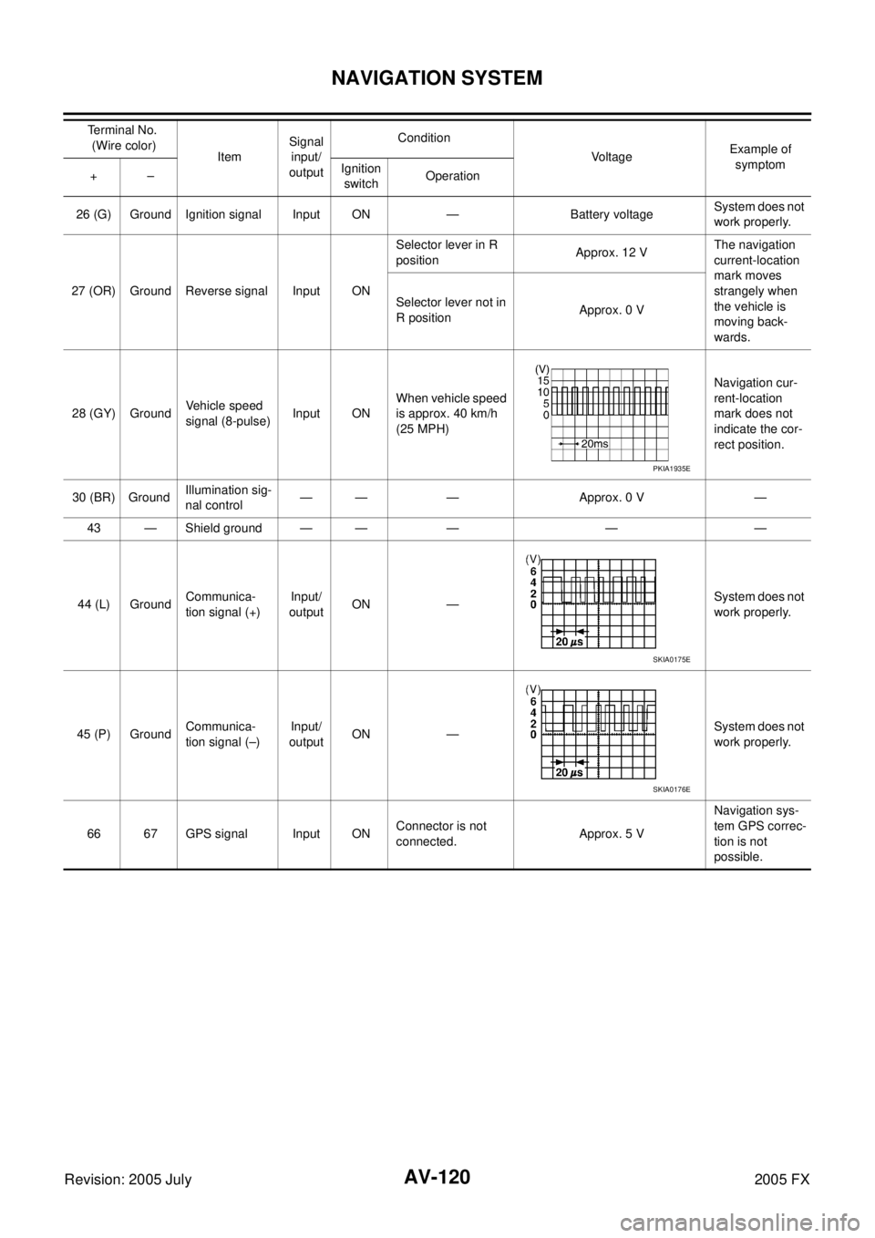
28 (GY) Ground Vehicle speed
signal (8-pulse) Input ON When vehicle speed
is approx. 40 km/h
(25 MPH) Navigation cur-
rent-location
mark does not
indicate the cor-
rect position.
30 (BR) Ground Illumination sig-
nal control — — — Approx. 0 V —
43 — Shield ground — — — — —
44 (L) Ground Communica-
tion signal (+) Input/
output ON —
System does not
work properly.
45 (P) Ground Communica-
tion signal (–) Input/
output ON — System does not
work properly.
66 67 GPS signal Input ON Connector is not
connected. Approx. 5 V Navigation sys-
tem GPS correc-
tion is not
possible.
Te r m i n a l N o .
(Wire color) Item Signal
input/
output Condition
Voltage Example of
symptom
+– Ignition
switch Operation
PKIA1935E
SKIA0175E
SKIA0176E
Page 720 of 4731

NAVIGATION SYSTEM AV-121
C
D E
F
G H
I
J
L
M A
B
AV
Revision: 2005 July 2005 FX
Terminals and Reference Value for Display Control UnitAKS007IW
Terminal No.
(Wire color) Item Signal
input/
output Condition
Voltage Example of
symptom
+– Ignition
switch Operation
1 (W/L) Ground Battery Power
supply Input OFF — Battery voltage System does not
work properly.
2 (W/G) Ground Power Sup-
ply (Inverter) Output ON — Approx. 9 V Screen is not
shown.
3 (B) Ground Ground — ON — Approx. 0 V —
4 (BR/W) Ground Power Sup-
ply (Signal) Output ON — Approx. 9 V
Screen is not
shown.
5 (P) Ground (Inverter)
Ground — ON — Approx. 0 V —
6 (OR) Ground Reverse
signal Input ON Selector lever in R
position Approx. 12 V
Impossible to
gain direction of
vehicle.
Selector lever not
in R position Approx. 0 V
7 (P/L) Ground (Signal)
Ground — ON — Approx. 0 V —
10 (LG/R) Ground ACC power
supply Input ACC — Battery voltage System does not
work properly.
12 (G/R) Ground Ignition signal Input ON — Battery voltage A/C operation is
not possible.
Vehicle informa-
tion setting is not
possible.
13 (B) Ground Sysco — ON — Approx. 0 V —
14 (R/L) Ground Illumination
signal Input OFF Lighting switch
position 1st or 2nd Approx. 12 V Audio unit illumi-
nation does not
come on when
lighting switch is
ON (position 1).
Lighting switch
position OFF Approx. 0 V
16 (R/G) Ground Vehicle speed
signal (8–
pulse) Input ON When vehicle
speed is approx.
40 km/h (25 MPH) Value of vehicle
information is
not accurately
displayed.
25 (L) — CAN H — — — — —
26 (R) — CAN L — — — — —
28 (B/R) Ground Communica-
tion signal (+) Input/
Output ON —
System does not
work properly.
29 — Shield ground — — — — —
PKIA1935E
SKIA0175E
Page 726 of 4731

NAVIGATION SYSTEM AV-127
C
D E
F
G H
I
J
L
M A
B
AV
Revision: 2005 July 2005 FX
Terminals and Reference Value for A/C and AV SwitchAKS007IY
Terminal No.
(Wire color) Item Signal
input/
output Condition
Vo l ta g e Example of
symptom
+– Ignition
switch Operation
1 (W/L) Ground Battery power
supply Input OFF — Battery voltage System does not
work properly.
2 (LG/R) Ground ACC power
supply Input ACC — Battery voltage System does not
work properly.
3 (R/L) Ground Illumination
signal Input OFF Lighting switch is
ON (position 1). Approx. 12 V
A/C and AV
switch illumina-
tion does not
come on when
lighting switch is
ON(position 1).
Turn lighting switch
OFF. Approx. 0 V
4 (R/Y) Ground Illumination
control signal Output ON Illumination control
switch is operated
by lighting switch in 1st or 2nd position. Changes between approx.0 V
and approx.12 V Audio unit illumi-
nation can not be
controlled.
5 (B) Ground Ground — ON — Approx. 0 V —
6 (B/R) Ground Communica-
tion signal (+) Input/
Output ON — System does not
work properly.
7— Shield
ground —— — — —
8 (W/R) Ground Communica-
tion signal (–) Input/
Output ON — System does not
work properly.
SKIA0175E
SKIA0176E
Page 741 of 4731
AV-142
NAVIGATION SYSTEM
Revision: 2005 July 2005 FX
Power Supply and Ground Circuit Check for NAVI Control UnitAKS007J5
1. CHECK FUSE
Make sure the following fuses of the NAVI control unit are not blown.
OK or NG
OK >> GO TO 2.
NG >> If fuse is blown, be sure to eliminate case of malfunction before installing new fuse. Refer to PG-3,
"POWER SUPPLY ROUTING CIRCUIT" .
2. CHECK POWER SUPPLY CIRCUIT
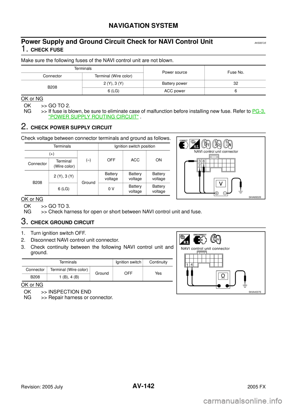
Check voltage between connector terminals and ground as follows.
OK or NG
OK >> GO TO 3.
NG >> Check harness for open or short between NAVI control unit and fuse.
3. CHECK GROUND CIRCUIT
1. Turn ignition switch OFF.
2. Disconnect NAVI control unit connector.
3. Check continuity between the following NAVI control unit and ground.
OK or NG
OK >> INSPECTION END
NG >> Repair harness or connector.
Terminals Power source Fuse No.
Connector Terminal (Wire color)
B208 2 (Y), 3 (Y) Battery power 32
6 (LG) ACC power 6
Terminals Ignition switch position
(+) (–) OFF ACC ON
Connector Te r m i n a l
(Wire color)
B208 2 (Y), 3 (Y)
Ground Battery
voltage Battery
voltage Battery
voltage
6 (LG) 0 V Battery
voltage Battery
voltage
SKIA8932E
Terminals Ignition switch Continuity
Connector Terminal (Wire color) Ground OFF Yes
B208 1 (B), 4 (B)
SKIA4037E
Page 742 of 4731
NAVIGATION SYSTEM AV-143
C
D E
F
G H
I
J
L
M A
B
AV
Revision: 2005 July 2005 FX
Power Supply and Ground Circuit Check for Display Control UnitAKS007J6
1. CHECK FUSE
Make sure the following fuses of the display control unit are not blown.
OK or NG
OK >> GO TO 2.
NG >> If fuse is blown, be sure to eliminate case of malfunction before installing new fuse. Refer to PG-3,
"POWER SUPPLY ROUTING CIRCUIT" .
2. CHECK POWER SUPPLY CIRCUIT
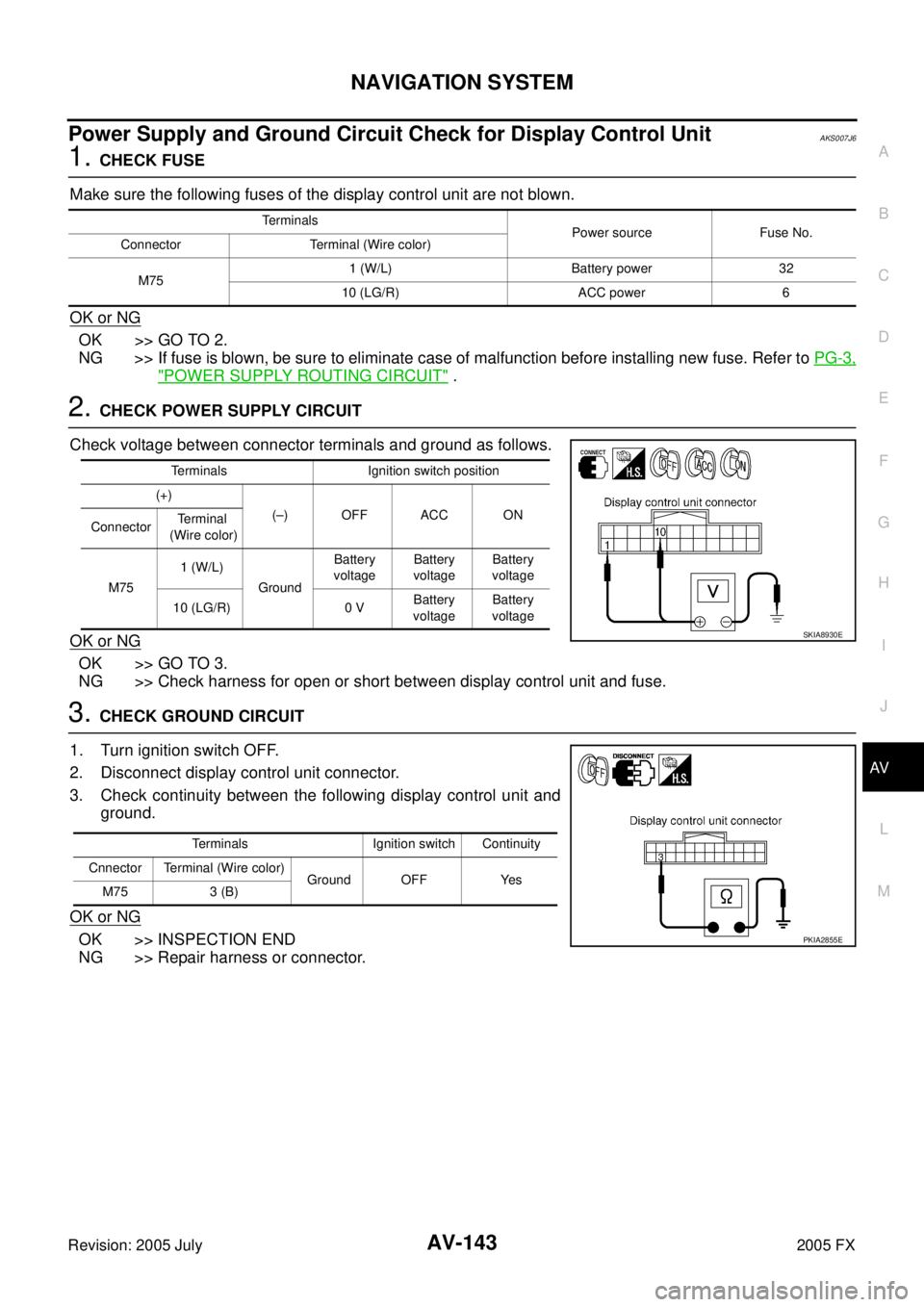
Check voltage between connector terminals and ground as follows.
OK or NG
OK >> GO TO 3.
NG >> Check harness for open or short between display control unit and fuse.
3. CHECK GROUND CIRCUIT
1. Turn ignition switch OFF.
2. Disconnect display control unit connector.
3. Check continuity between the following display control unit and ground.
OK or NG
OK >> INSPECTION END
NG >> Repair harness or connector.
Terminals Power source Fuse No.
Connector Terminal (Wire color)
M75 1 (W/L) Battery power 32
10 (LG/R) ACC power 6
Terminals Ignition switch position
(+) (–) OFF ACC ON
Connector Terminal
(Wire color)
M75 1 (W/L)
Ground Battery
voltage Battery
voltage Battery
voltage
10 (LG/R) 0 V Battery
voltage Battery
voltage
SKIA8930E
Terminals Ignition switch Continuity
Cnnector Terminal (Wire color) Ground OFF Yes
M75 3 (B)
PKIA2855E
Page 744 of 4731
NAVIGATION SYSTEM AV-145
C
D E
F
G H
I
J
L
M A
B
AV
Revision: 2005 July 2005 FX
Power Supply and Ground Circuit Check for A/C and AV SwitchAKS007J8
1. CHECK FUSE
Make sure the following fuses of the A/C and AV switch are not blown.
OK or NG
OK >> GO TO 2.
NG >> If fuse is blown, be sure to eliminate case of malfunction before installing new fuse. Refer to PG-3,
"POWER SUPPLY ROUTING CIRCUIT" .
2. CHECK POWER SUPPLY CIRCUIT
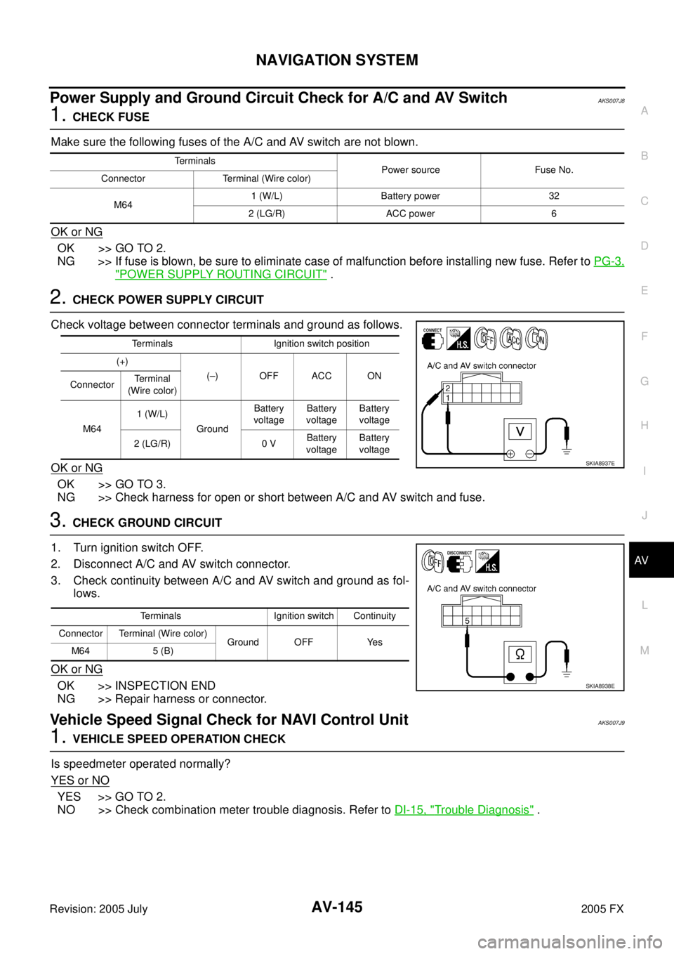
Check voltage between connector terminals and ground as follows.
OK or NG
OK >> GO TO 3.
NG >> Check harness for open or short between A/C and AV switch and fuse.
3. CHECK GROUND CIRCUIT
1. Turn ignition switch OFF.
2. Disconnect A/C and AV switch connector.
3. Check continuity between A/C and AV switch and ground as fol- lows.
OK or NG
OK >> INSPECTION END
NG >> Repair harness or connector.
Vehicle Speed Signal Check for NAVI Control UnitAKS007J9
1. VEHICLE SPEED OPERATION CHECK
Is speedmeter operated normally?
YES or NO
YES >> GO TO 2.
NO >> Check combination meter trouble diagnosis. Refer to DI-15, "
Trouble Diagnosis" .
Terminals
Power source Fuse No.
Connector Terminal (Wire color)
M64 1 (W/L) Battery power 32
2 (LG/R) ACC power 6
Terminals Ignition switch position
(+) (–) OFF ACC ON
Connector Te r m i n a l
(Wire color)
M64 1 (W/L)
Ground Battery
voltage Battery
voltage Battery
voltage
2 (LG/R) 0 V Battery
voltage Battery
voltage
SKIA8937E
Terminals Ignition switch Continuity
Connector Terminal (Wire color) Ground OFF Yes
M64 5 (B)
SKIA8938E
Page 747 of 4731
AV-148
NAVIGATION SYSTEM
Revision: 2005 July 2005 FX
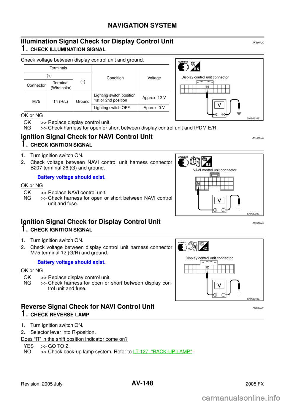
Illumination Signal Check for Display Control Unit AKS007JC
1. CHECK ILLUMINATION SIGNAL
Check voltage between display control unit and ground.
OK or NG
OK >> Replace display control unit.
NG >> Check harness for open or short between display control unit and IPDM E/R.
Ignition Signal Check for NAVI Control UnitAKS007JD
1. CHECK IGNITION SIGNAL
1. Turn ignition switch ON.
2. Check voltage between NAVI control unit harness connector B207 terminal 26 (G) and ground.
OK or NG
OK >> Replace NAVI control unit.
NG >> Check harness for open or short between NAVI control unit and fuse.
Ignition Signal Check for Display Control UnitAKS007JE
1. CHECK IGNITION SIGNAL
1. Turn ignition switch ON.
2. Check voltage between display control unit harness connector M75 terminal 12 (G/R) and ground.
OK or NG
OK >> Replace display control unit.
NG >> Check harness for open or short between display con-
trol unit and fuse.
Reverse Signal Check for NAVI Control UnitAKS007JF
1. CHECK REVERSE LAMP
1. Turn ignition switch ON.
2. Selector lever into R-position.
Does
“R” in the shift position indicator come on?
YES >> GO TO 2.
NO >> Check back-up lamp system. Refer to LT- 1 2 7 , "
BACK-UP LAMP" .
Terminals
Condition Voltage
(+)
(–)
Connector Te r m i n a l
(Wire color)
M75 14 (R/L) Ground Lighting switch position
1st or 2nd position Approx. 12 V
Lighting switch OFF Approx. 0 V
SKIB0316E
Battery voltage should exist.
SKIA8939E
Battery voltage should exist.
SKIA8940E
Page 785 of 4731
AV-186
INFINITI MOBILE ENTERTAINMENT SYSTEM
Revision: 2005 July 2005 FX
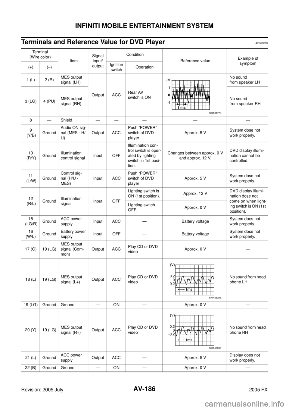
Terminals and Reference Value for DVD PlayerAKS007WJ
Terminal
(Wire color) Item Signal
input/
output Condition
Reference value Example of
symptom
(+) (–) Ignition
switch Operation
1 (L) 2 (R) MES output
signal (LH)
Output ACC Rear AV
switch is ON No sound
from speaker LH
3 (LG) 4 (PU) MES output
signal (RH) No sound
from speaker RH
8—Shield —— — — —
9
(Y/B) Ground Audio ON sig-
nal (MES - H/
U) Output ACC Push “POWER”
switch of DVD
player Approx. 5 V
System dose not
work properly.
10
(R/Y) Ground Illumination
control signal Input OFF Illumination con-
trol switch is oper-
ated by lighting
switch in 1st posi-
tion. Changes between approx. 0 V
and approx. 12 V. DVD display illumi-
nation cannot be
controlled.
11
(L/W) Ground Control sig-
nal (H/U -
MES) Input ACC Push “POWER”
switch of DVD
player Approx. 5 V
System dose not
work properly.
12
(R/L) Ground Illumination
signal Input OFF Lighting switch is
ON (1st position). Approx. 12 V DVD display illumi-
nation dose not
come on when light-
ing switch is ON (1st
position).
Lighting switch
OFF. Approx. 0 V
15
(LG/R) GroundACC power
supply Input ACC — Battery voltage System does not
work properly.
16
(W/L) Ground
Battery power
supply Input OFF — Battery voltage
System dose not
work properly.
17 (G) 19 (LG) MES output
signal (Com-
mon) Output ACC
Play CD or DVD
video Approx. 0 V —
18 (L) 19 (LG) MES output
signal (L+) Output ACC
Play CD or DVD
video No sound from head
phone LH
19 (LG) Ground Ground — ON — Approx. 0 V —
20 (Y) 19 (LG) MES output
signal (R+) Output ACC Play CD or DVD
video No sound from head
phone RH
21 (L) Ground ACC power
supply Output ACC — Approx. 5 V Display does not
work properly.
22 (B) Ground Ground — ON — Approx. 0 V —
SKIA0177E
SKIA5828E
SKIA5828E