Page 4074 of 4731

INTERIOR ROOM LAMP LT-185
C
D E
F
G H
I
J
L
M A
B
LT
Revision: 2005 July 2005 FX
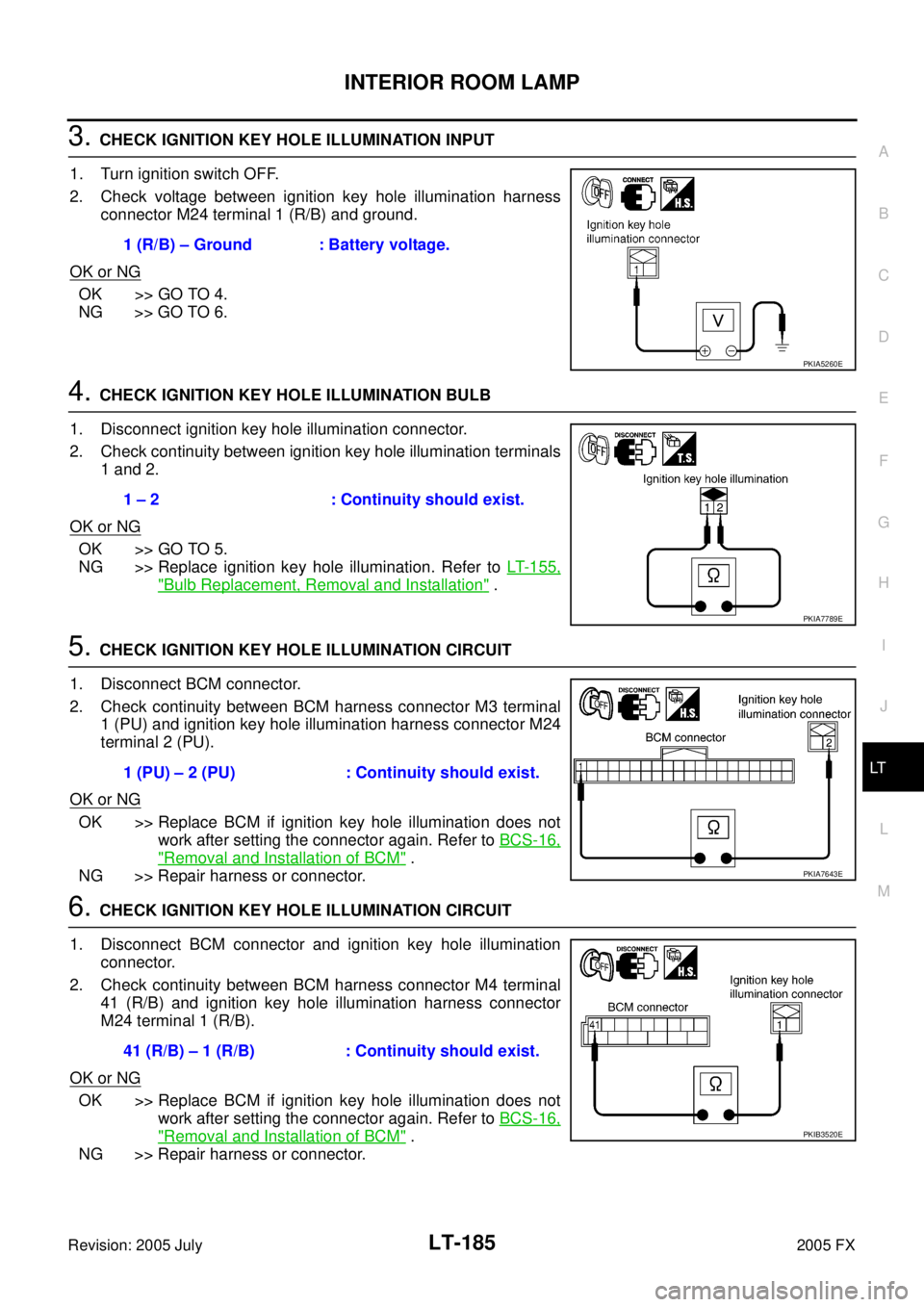
3. CHECK IGNITION KEY HOLE ILLUMINATION INPUT
1. Turn ignition switch OFF.
2. Check voltage between ignition key hole illumination harness connector M24 terminal 1 (R/B) and ground.
OK or NG
OK >> GO TO 4.
NG >> GO TO 6.
4. CHECK IGNITION KEY HOLE ILLUMINATION BULB
1. Disconnect ignition key hole illumination connector.
2. Check continuity between ignition key hole illumination terminals 1 and 2.
OK or NG
OK >> GO TO 5.
NG >> Replace ignition key hole illumination. Refer to LT- 1 5 5 ,
"Bulb Replacement, Removal and Installation" .
5. CHECK IGNITION KEY HOLE ILLUMINATION CIRCUIT
1. Disconnect BCM connector.
2. Check continuity between BCM harness connector M3 terminal 1 (PU) and ignition key hole illumination harness connector M24
terminal 2 (PU).
OK or NG
OK >> Replace BCM if ignition key hole illumination does not work after setting the connector again. Refer to BCS-16,
"Removal and Installation of BCM" .
NG >> Repair harness or connector.
6. CHECK IGNITION KEY HOLE ILLUMINATION CIRCUIT
1. Disconnect BCM connector and ignition key hole illumination connector.
2. Check continuity between BCM harness connector M4 terminal 41 (R/B) and ignition key hole illumination harness connector
M24 terminal 1 (R/B).
OK or NG
OK >> Replace BCM if ignition key hole illumination does not work after setting the connector again. Refer to BCS-16,
"Removal and Installation of BCM" .
NG >> Repair harness or connector. 1 (R/B) – Ground : Battery voltage.
PKIA5260E
1 – 2 : Continuity should exist.
PKIA7789E
1 (PU) – 2 (PU) : Continuity should exist.
PKIA7643E
41 (R/B) – 1 (R/B) : Continuity should exist.
PKIB3520E
Page 4076 of 4731

INTERIOR ROOM LAMP LT-187
C
D E
F
G H
I
J
L
M A
B
LT
Revision: 2005 July 2005 FX
4. CHECK STEP LAMP CIRCUIT
1. Disconnect BCM connector and front door driver side step lamp connector.
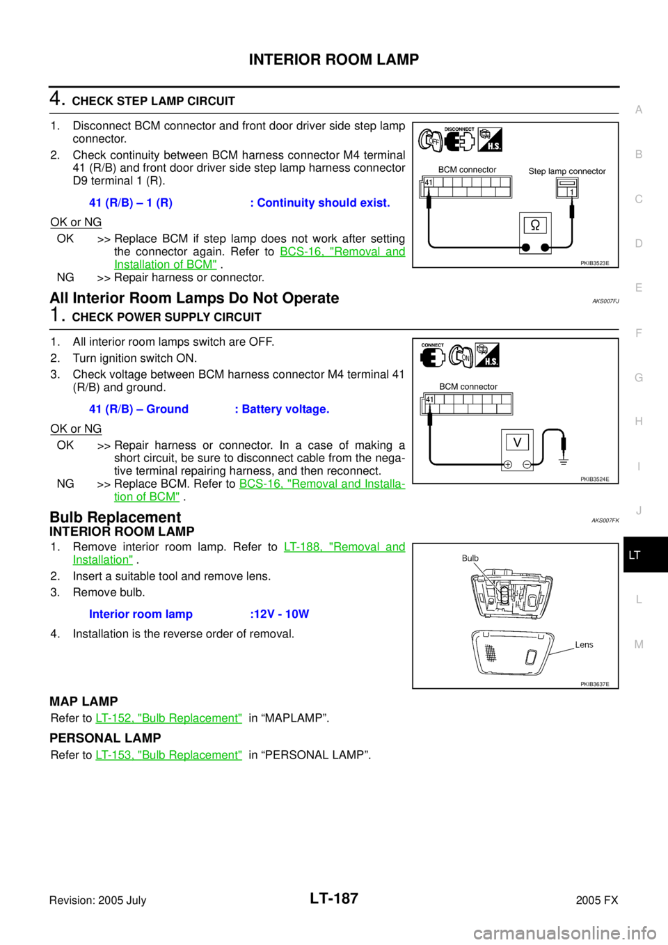
2. Check continuity between BCM harness connector M4 terminal 41 (R/B) and front door driver side step lamp harness connector
D9 terminal 1 (R).
OK or NG
OK >> Replace BCM if step lamp does not work after setting the connector again. Refer to BCS-16, "
Removal and
Installation of BCM" .
NG >> Repair harness or connector.
All Interior Room Lamps Do Not OperateAKS007FJ
1. CHECK POWER SUPPLY CIRCUIT
1. All interior room lamps switch are OFF.
2. Turn ignition switch ON.
3. Check voltage between BCM harness connector M4 terminal 41 (R/B) and ground.
OK or NG
OK >> Repair harness or connector. In a case of making a short circuit, be sure to disconnect cable from the nega-
tive terminal repairing harness, and then reconnect.
NG >> Replace BCM. Refer to BCS-16, "
Removal and Installa-
tion of BCM" .
Bulb ReplacementAKS007FK
INTERIOR ROOM LAMP
1. Remove interior room lamp. Refer to LT- 1 8 8 , "Removal and
Installation" .
2. Insert a suitable tool and remove lens.
3. Remove bulb.
4. Installation is the reverse order of removal.
MAP LAMP
Refer to LT- 1 5 2 , "Bulb Replacement" in “MAPLAMP”.
PERSONAL LAMP
Refer to LT- 1 5 3 , "Bulb Replacement" in “PERSONAL LAMP”.
41 (R/B) – 1 (R) : Continuity should exist.
PKIB3523E
41 (R/B) – Ground : Battery voltage.
PKIB3524E
Interior room lamp :12V - 10W
PKIB3637E
Page 4091 of 4731
LT-202
ILLUMINATION
Revision: 2005 July 2005 FX
Removal and InstallationAKS007EN
ILLUMINATION CONTROL SWITCH
Refer to DI-27, "Removal and Installation of Odo/Trip Meter and Illumination Control Switch" in “DI” section.
GLOVE BOX LAMP
Refer to LT- 1 5 6 , "Bulb Replacement, Removal and Installation" .
FRONT DOOR INSIDE ILLUMINATION
Refer to EI-34, "Removal and Installation" in “EI” section.
Page 4092 of 4731
BULB SPECIFICATIONS LT-203
C
D E
F
G H
I
J
L
M A
B
LT
Revision: 2005 July 2005 FX
BULB SPECIFICATIONSPFP:26297
HeadlampAKS007EO
Exterior LampAKS007EP
Interior Lamp/IlluminationAKS007EQ
Item Wattage (W)
High/Low (Xenon type) 35 (D2S)
Item Wattage (W)
Front combination lamp Front turn signal lamp 21 (amber)
Daytime/Parking lamp 21/5
Front side marker lamp 3.8
Rear combination lamp Stop/Tail lamp and Rear Turn signal
lamp LED
Rear side marker lamp 3.8
Front fog lamp 51 (HB4)
Back-up lamp 18
License plate lamp 5
High-mounted stop lamp (back door mount) LED
Item Wattage (W)
Map lamp 8
Interior room lamp 10
Personal lamp 8
Luggage room lamp 8
Step lamp 5
Glove box lamp 1.4
Vanity mirror lamp 1.32
Ignition key hole illumination 0.8
Front door inside handle illumination LED
Rear door inside handle illumination LED
Console illumination lamp 1.4
Page 4093 of 4731
LT-204
BULB SPECIFICATIONS
Revision: 2005 July 2005 FX
Page 4201 of 4731

PG-24
IPDM E/R (INTELLIGENT POWER DISTRIBUTION MODULE ENGINE ROOM)
Revision: 2005 July 2005 FX
Auto Active TestAKS005SD
DESCRIPTION
In auto active test mode, operation inspection can be performed when IPDM E/R sends a drive signal to the
following systems:
�Rear window defogger
�Front wipers
�Parking, license plate and tail lamps
�Front fog lamps
�Headlamps (Hi, Lo)
�A/C compressor (magnetic clutch)
�Cooling fan
OPERATION PROCEDURE
1. Close hood and front door (passenger side), and then lift wiper arms away from windshield (to prevent glass damage by wiper operation).
NOTE:
When auto active test is performed with hood opened, sprinkle water on windshield beforehand.
2. Turn ignition switch OFF.
3. Turn ignition switch ON, and within 20 seconds, press drivers door switch 10 times (close other doors). Then turn ignition switch OFF.
4. Turn ignition switch ON within 10 seconds after ignition switch OFF.
5. When auto active test mode is actuated, horn chirps once oil pressure warning lamp starts blinking.
6. After a series of operations is repeated three times, auto active test is completed. NOTE:
When auto active test mode has to be cancelled halfway, turn ignition switch OFF.
CAUTION:
Be sure to inspect BL-42, "
Check Door Switch" when the auto active test cannot be performed.
INSPECTION IN AUTO ACTIVE TEST MODE
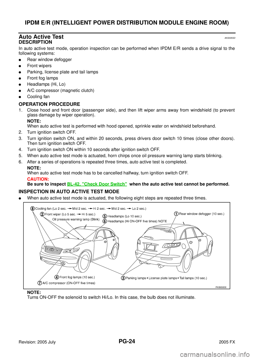
�When auto active test mode is actuated, the following eight steps are repeated three times.
NOTE:
Turns ON-OFF the solenoid to switch Hi/Lo. In this case, the bulb does not illuminate.
PKIB6583E