Page 3326 of 4731
POWER WINDOW SYSTEM GW-49
C
D E
F
G H
J
K L
M A
B
GW
Revision: 2005 July 2005 FX
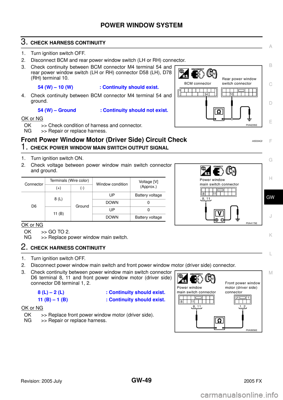
3. CHECK HARNESS CONTINUITY
1. Turn ignition switch OFF.
2. Disconnect BCM and rear power window switch (LH or RH) connector.
3. Check continuity between BCM connector M4 terminal 54 and rear power window switch (LH or RH) connector D58 (LH), D78
(RH) terminal 10.
4. Check continuity between BCM connector M4 terminal 54 and ground.
OK or NG
OK >> Check condition of harness and connector.
NG >> Repair or replace harness.
Front Power Window Motor (Driver Side) Circuit CheckAIS004QI
1. CHECK POWER WINDOW MAIN SWITCH OUTPUT SIGNAL
1. Turn ignition switch ON.
2. Check voltage between power window main switch connector and ground.
OK or NG
OK >> GO TO 2.
NG >> Replace power window main switch.
2. CHECK HARNESS CONTINUITY
1. Turn ignition switch OFF.
2. Disconnect power window main switch and front power window motor (driver side) connector.
3. Check continuity between power window main switch connector D6 terminal 8, 11 and front power window motor (driver side)
connector D8 terminal 1, 2.
OK or NG
OK >> Replace front power window motor (driver side).
NG >> Repair or replace harness. 54 (W) – 10 (W) : Continuity should exist.
54 (W) – Ground : Continuity should not exist.
PIIA6295E
Connector Terminals (Wire color)
Window condition Voltage [V]
(Approx.)
(+) (-)
D6 8 (L)
Ground UP Battery voltage
DOWN 0
11 ( B ) UP 0
DOWN Battery voltage
PIIA4179E
8 (L) – 2 (L) : Continuity should exist.
11 (B) – 1 (B) : Continuity should exist.
PIIA9956E
Page 3327 of 4731
GW-50
POWER WINDOW SYSTEM
Revision: 2005 July 2005 FX
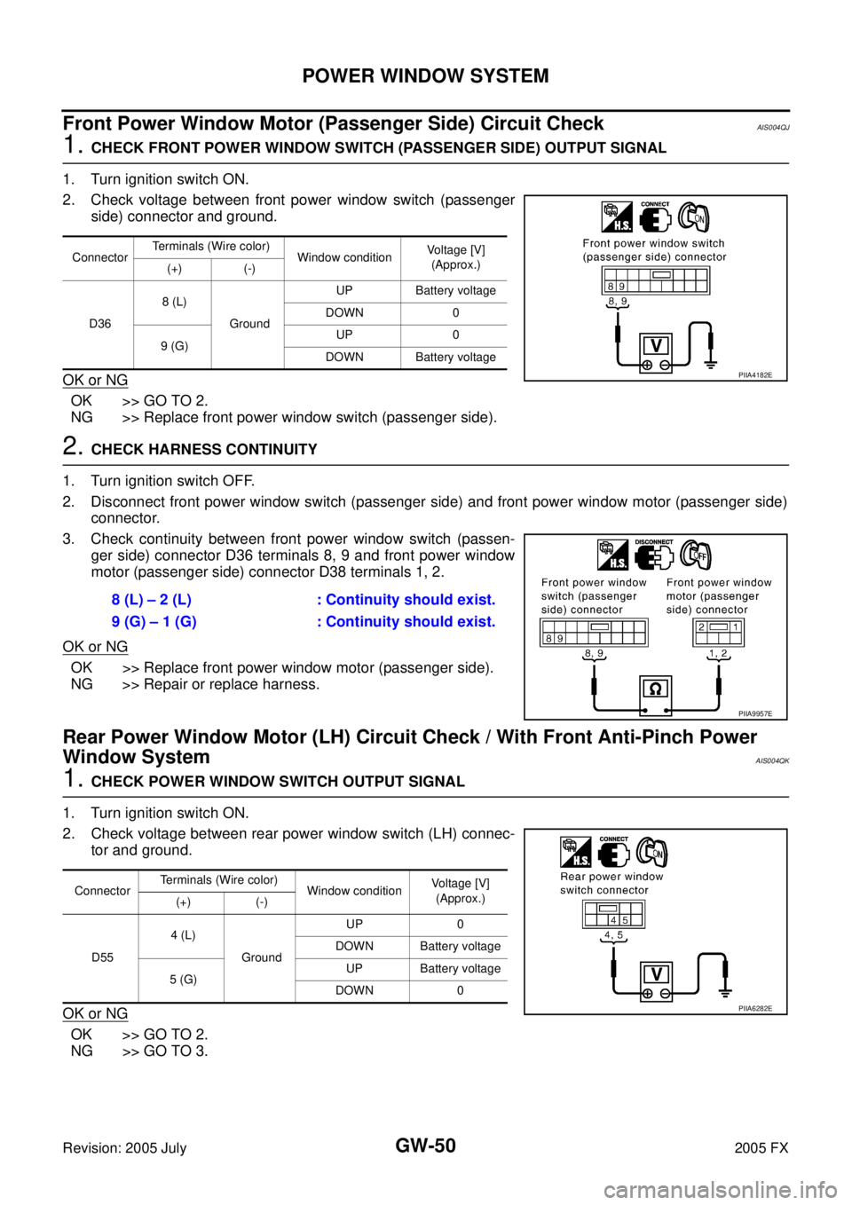
Front Power Window Motor (Passenger Side) Circuit CheckAIS004QJ
1. CHECK FRONT POWER WINDOW SWITCH (PASSENGER SIDE) OUTPUT SIGNAL
1. Turn ignition switch ON.
2. Check voltage between front power window switch (passenger side) connector and ground.
OK or NG
OK >> GO TO 2.
NG >> Replace front power window switch (passenger side).
2. CHECK HARNESS CONTINUITY
1. Turn ignition switch OFF.
2. Disconnect front power window switch (passenger side) and front power window motor (passenger side) connector.
3. Check continuity between front power window switch (passen- ger side) connector D36 terminals 8, 9 and front power window
motor (passenger side) connector D38 terminals 1, 2.
OK or NG
OK >> Replace front power window motor (passenger side).
NG >> Repair or replace harness.
Rear Power Window Motor (LH) Circuit Check / With Front Anti-Pinch Power
Window System
AIS004QK
1. CHECK POWER WINDOW SWITCH OUTPUT SIGNAL
1. Turn ignition switch ON.
2. Check voltage between rear power window switch (LH) connec- tor and ground.
OK or NG
OK >> GO TO 2.
NG >> GO TO 3.
Connector Terminals (Wire color)
Window condition Voltage [V]
(Approx.)
(+) (-)
D36 8 (L)
Ground UP Battery voltage
DOWN 0
9 (G) UP 0
DOWN Battery voltage
PIIA4182E
8 (L) – 2 (L) : Continuity should exist.
9 (G) – 1 (G) : Continuity should exist.
PIIA9957E
Connector Terminals (Wire color)
Window condition Voltage [V]
(Approx.)
(+) (-)
D55 4 (L)
Ground UP 0
DOWN Battery voltage
5 (G) UP Battery voltage
DOWN 0
PIIA6282E
Page 3328 of 4731

POWER WINDOW SYSTEM GW-51
C
D E
F
G H
J
K L
M A
B
GW
Revision: 2005 July 2005 FX
2. CHECK HARNESS CONTINUITY 1
1. Turn ignition switch OFF.
2. Disconnect rear power window switch (LH) and rear power window motor (LH) connector.
3. Check continuity between rear power window switch (LH) con- nector D55 terminal 4, 5 and rear power window motor (LH) con-
nector D56 terminal 1, 2.
OK or NG
OK >> Replace rear power window motor (LH).
NG >> Repair or replace harness.
3. CHECK REAR POWER WINDOW SWITCH POWER SUPPLY
1. Connect rear power window switch (LH) connector.
2. Turn ignition switch ON.
3. Check voltage between rear power window switch (LH) connec- tor D55 terminal 1 and ground.
OK or NG
OK >> GO TO 5.
NG >> GO TO 4.
4. CHECK HARNESS CONTINUITY 2
1. Turn ignition switch OFF.
2. Disconnect BCM and rear power window switch (LH) connector.
3. Check continuity between BCM connector M4 terminal 53 and rear power window switch (LH) connector D55 terminal 1.
4. Check continuity between BCM connector M4 terminal 53 and ground.
OK or NG
OK >> Check condition of harness and connector.
NG >> Repair or replace harness. 4 (L) – 1 (L) : Continuity should exist.
5 (G) – 2 (G) : Continuity should exist.
PIIA9958E
1 (BR) – Ground : Battery voltage
PIIA4185E
53 (Y/B) – 1 (BR) : Continuity should exist.
53 (Y/B) – Ground : Continuity should not exist.
PIIA6284E
Page 3329 of 4731
GW-52
POWER WINDOW SYSTEM
Revision: 2005 July 2005 FX
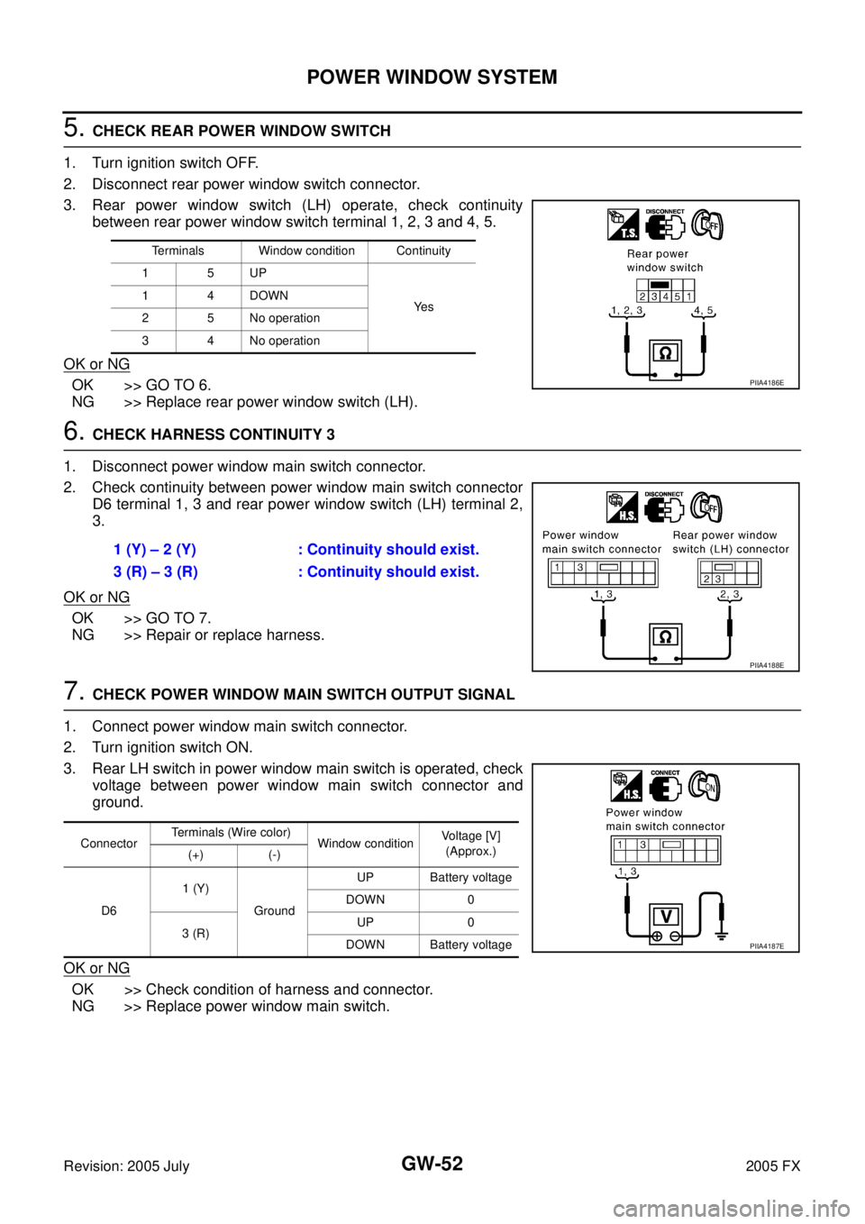
5. CHECK REAR POWER WINDOW SWITCH
1. Turn ignition switch OFF.
2. Disconnect rear power window switch connector.
3. Rear power window switch (LH) operate, check continuity between rear power window switch terminal 1, 2, 3 and 4, 5.
OK or NG
OK >> GO TO 6.
NG >> Replace rear power window switch (LH).
6. CHECK HARNESS CONTINUITY 3
1. Disconnect power window main switch connector.
2. Check continuity between power window main switch connector D6 terminal 1, 3 and rear power window switch (LH) terminal 2,
3.
OK or NG
OK >> GO TO 7.
NG >> Repair or replace harness.
7. CHECK POWER WINDOW MAIN SWITCH OUTPUT SIGNAL
1. Connect power window main switch connector.
2. Turn ignition switch ON.
3. Rear LH switch in power window main switch is operated, check voltage between power window main switch connector and
ground.
OK or NG
OK >> Check condition of harness and connector.
NG >> Replace power window main switch.
Terminals Window condition Continuity
15UP
Ye s
14DOWN
2 5 No operation
3 4 No operation
PIIA4186E
1 (Y) – 2 (Y) : Continuity should exist.
3 (R) – 3 (R) : Continuity should exist.
PIIA4188E
Connector Terminals (Wire color)
Window condition Voltage [V]
(Approx.)
(+) (-)
D6 1 (Y)
Ground UP Battery voltage
DOWN 0
3 (R) UP 0
DOWN Battery voltage
PIIA4187E
Page 3330 of 4731
POWER WINDOW SYSTEM GW-53
C
D E
F
G H
J
K L
M A
B
GW
Revision: 2005 July 2005 FX
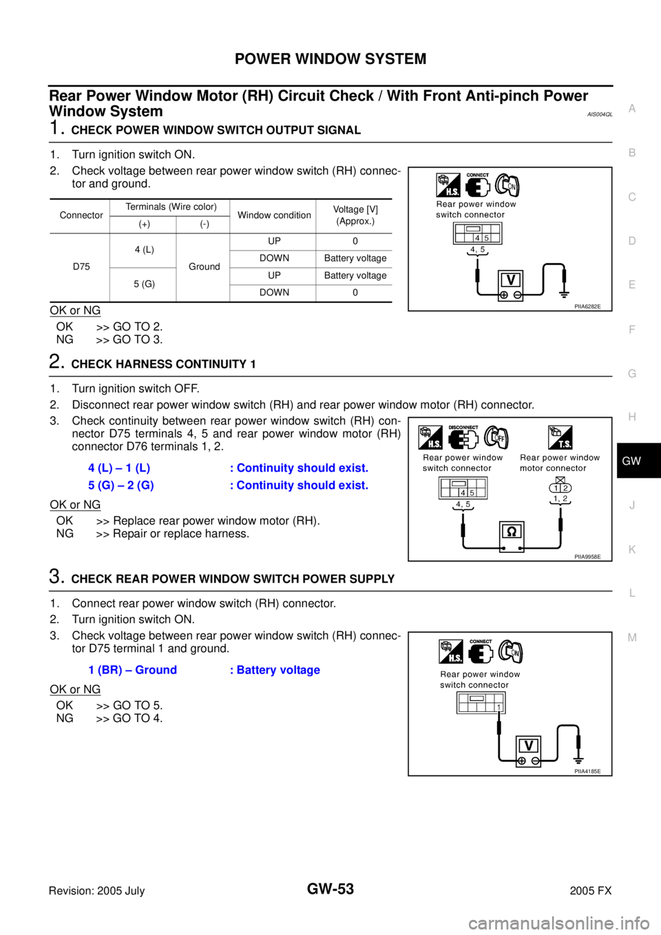
Rear Power Window Motor (RH) Circuit Check / With Front Anti-pinch Power
Window System
AIS004QL
1. CHECK POWER WINDOW SWITCH OUTPUT SIGNAL
1. Turn ignition switch ON.
2. Check voltage between rear power window switch (RH) connec- tor and ground.
OK or NG
OK >> GO TO 2.
NG >> GO TO 3.
2. CHECK HARNESS CONTINUITY 1
1. Turn ignition switch OFF.
2. Disconnect rear power window switch (RH) and rear power window motor (RH) connector.
3. Check continuity between rear power window switch (RH) con- nector D75 terminals 4, 5 and rear power window motor (RH)
connector D76 terminals 1, 2.
OK or NG
OK >> Replace rear power window motor (RH).
NG >> Repair or replace harness.
3. CHECK REAR POWER WINDOW SWITCH POWER SUPPLY
1. Connect rear power window switch (RH) connector.
2. Turn ignition switch ON.
3. Check voltage between rear power window switch (RH) connec- tor D75 terminal 1 and ground.
OK or NG
OK >> GO TO 5.
NG >> GO TO 4.
Connector Terminals (Wire color)
Window condition Voltage [V]
(Approx.)
(+) (-)
D75 4 (L)
Ground UP 0
DOWN Battery voltage
5 (G) UP Battery voltage
DOWN 0
PIIA6282E
4 (L) – 1 (L) : Continuity should exist.
5 (G) – 2 (G) : Continuity should exist.
PIIA9958E
1 (BR) – Ground : Battery voltage
PIIA4185E
Page 3332 of 4731
POWER WINDOW SYSTEM GW-55
C
D E
F
G H
J
K L
M A
B
GW
Revision: 2005 July 2005 FX
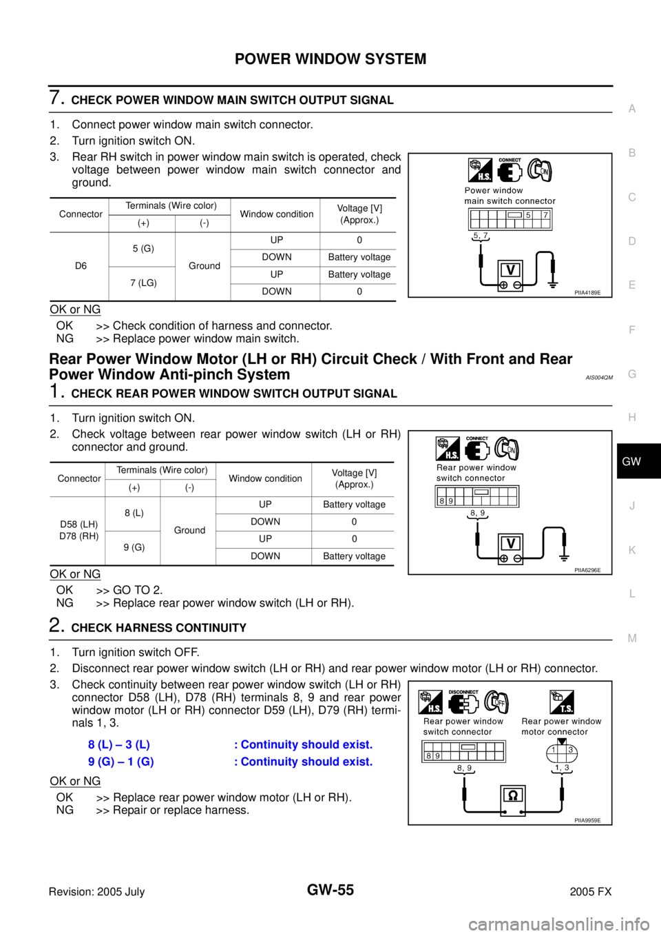
7. CHECK POWER WINDOW MAIN SWITCH OUTPUT SIGNAL
1. Connect power window main switch connector.
2. Turn ignition switch ON.
3. Rear RH switch in power window main switch is operated, check voltage between power window main switch connector and
ground.
OK or NG
OK >> Check condition of harness and connector.
NG >> Replace power window main switch.
Rear Power Window Motor (LH or RH) Circuit Check / With Front and Rear
Power Window Anti-pinch System
AIS004QM
1. CHECK REAR POWER WINDOW SWITCH OUTPUT SIGNAL
1. Turn ignition switch ON.
2. Check voltage between rear power window switch (LH or RH) connector and ground.
OK or NG
OK >> GO TO 2.
NG >> Replace rear power window switch (LH or RH).
2. CHECK HARNESS CONTINUITY
1. Turn ignition switch OFF.
2. Disconnect rear power window switch (LH or RH) and rear power window motor (LH or RH) connector.
3. Check continuity between rear power window switch (LH or RH) connector D58 (LH), D78 (RH) terminals 8, 9 and rear power
window motor (LH or RH) connector D59 (LH), D79 (RH) termi-
nals 1, 3.
OK or NG
OK >> Replace rear power window motor (LH or RH).
NG >> Repair or replace harness.
Connector Terminals (Wire color)
Window condition Voltage [V]
(Approx.)
(+) (-)
D6 5 (G)
Ground UP 0
DOWN Battery voltage
7 (LG) UP Battery voltage
DOWN 0
PIIA4189E
Connector Terminals (Wire color)
Window condition Voltage [V]
(Approx.)
(+) (-)
D58 (LH)
D78 (RH) 8 (L)
Ground UP Battery voltage
DOWN 0
9 (G) UP 0
DOWN Battery voltage
PIIA6296E
8 (L) – 3 (L) : Continuity should exist.
9 (G) – 1 (G) : Continuity should exist.
PIIA9959E
Page 3344 of 4731
POWER WINDOW SYSTEM GW-67
C
D E
F
G H
J
K L
M A
B
GW
Revision: 2005 July 2005 FX
Door Switch Check AIS004QT
1. CHECK DOOR SWITCH INPUT SIGNAL
With CONSULT-II
Check (“DOOR SW-DR” and “DOOR SW-AS”) in “DATA MONITOR” mode with CONSULT-II.
Without CONSULT-II
Check voltage between BCM connector M3, B14 terminals 12, 62 and ground.
OK or NG
OK >> Door switch is OK.
NG >> GO TO 2.
Monitor item Condition
DOOR SW-DR OPEN : ON
CLOSE : OFF
DOOR SW-AS OPEN : ON
CLOSE : OFF
PIIA2464E
Item Terminals (Wire color)
Door condition Voltage [V]
(Approx.)
(+) (–)
Passenger side
door switch 12 (P/B)
Ground OPEN 0
CLOSE Battery voltage
Driver side door
switch 62 (W) OPEN 0
CLOSE Battery voltage
PIIA6158E
Page 3345 of 4731
GW-68
POWER WINDOW SYSTEM
Revision: 2005 July 2005 FX
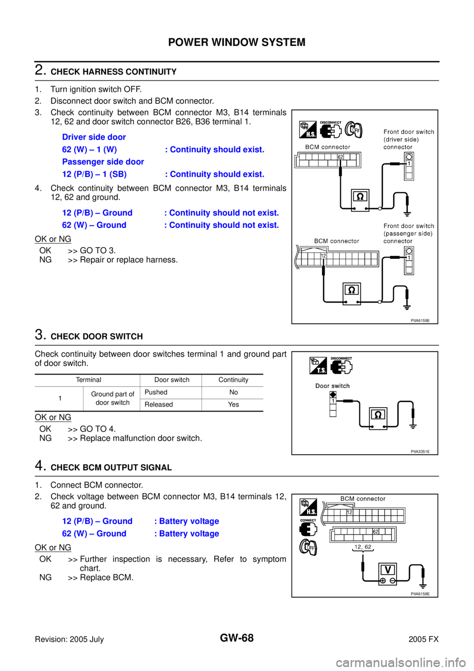
2. CHECK HARNESS CONTINUITY
1. Turn ignition switch OFF.
2. Disconnect door switch and BCM connector.
3. Check continuity between BCM connector M3, B14 terminals 12, 62 and door switch connector B26, B36 terminal 1.
4. Check continuity between BCM connector M3, B14 terminals 12, 62 and ground.
OK or NG
OK >> GO TO 3.
NG >> Repair or replace harness.
3. CHECK DOOR SWITCH
Check continuity between door switches terminal 1 and ground part
of door switch.
OK or NG
OK >> GO TO 4.
NG >> Replace malfunction door switch.
4. CHECK BCM OUTPUT SIGNAL
1. Connect BCM connector.
2. Check voltage between BCM connector M3, B14 terminals 12, 62 and ground.
OK or NG
OK >> Further inspection is necessary, Refer to symptom chart.
NG >> Replace BCM. Driver side door
62 (W) – 1 (W) : Continuity should exist.
Passenger side door
12 (P/B) – 1 (SB) : Continuity should exist.
12 (P/B) – Ground : Continuity should not exist.
62 (W) – Ground : Continuity should not exist.
PIIA6159E
Terminal Door switch Continuity
1 Ground part of
door switch Pushed No
Released Yes
PIIA3351E
12 (P/B) – Ground : Battery voltage
62 (W) – Ground : Battery voltage
PIIA6158E