Page 1256 of 4731
![INFINITI FX35 2005 Service Manual WATER PUMP CO-51
[VK45DE]
C
D E
F
G H
I
J
K L
M A
CO
Revision: 2005 July 2005 FX
WAT E R P U MPPFP:21020
Removal and InstallationABS006JO
CAUTION:
�When removing water pump, be careful n](/manual-img/42/57020/w960_57020-1255.png "INFINITI FX35 2005 Service Manual WATER PUMP CO-51
[VK45DE]
C
D E
F
G H
I
J
K L
M A
CO
Revision: 2005 July 2005 FX
WAT E R P U MPPFP:21020
Removal and InstallationABS006JO
CAUTION:
�When removing water pump, be careful n")
WATER PUMP CO-51
[VK45DE]
C
D E
F
G H
I
J
K L
M A
CO
Revision: 2005 July 2005 FX
WAT E R P U MPPFP:21020
Removal and InstallationABS006JO
CAUTION:
�When removing water pump, be careful not to get engine coolant on drive belts.
�Water pump can not be disassembled and should be replaced as a unit.
�After installing water pump, connect hose and clamp securely, then check for leaks using radiator
cap tester (commercial service tool) and radiator cap tester adapter [SST: EG17650301 (J33984-
A)].
REMOVAL
1. Drain engine coolant from drain plugs on radiator and both side of cylinder block. Refer to CO-37, "Chang-
ing Engine Coolant" and EM-246, "DISASSEMBLY" .
CAUTION:
�Perform this step when engine is cold.
�Do not spill engine coolant on drive belts.
2. Remove following parts:
�Engine front undercover
�Air duct (inlet); Refer to EM-176, "AIR CLEANER AND AIR DUCT" .
�Alternator, water pump and A/C compressor belt; Refer to EM-173, "DRIVE BELTS" .
3. Remove fan coupling with cooling fan, and then water pump pulley.
4. Remove water pump.
�Engine coolant will leak from cylinder block, so have a receptacle ready under vehicle.
CAUTION:
�Handle the water pump vane so that it does not contact any other parts.
�Do not disassemble water pump.
1. Water pump pulley 2. Water pump 3. Gasket
PBIC1538E
Page 1257 of 4731
CO-52
[VK45DE]
WATER PUMP
Revision: 2005 July 2005 FX
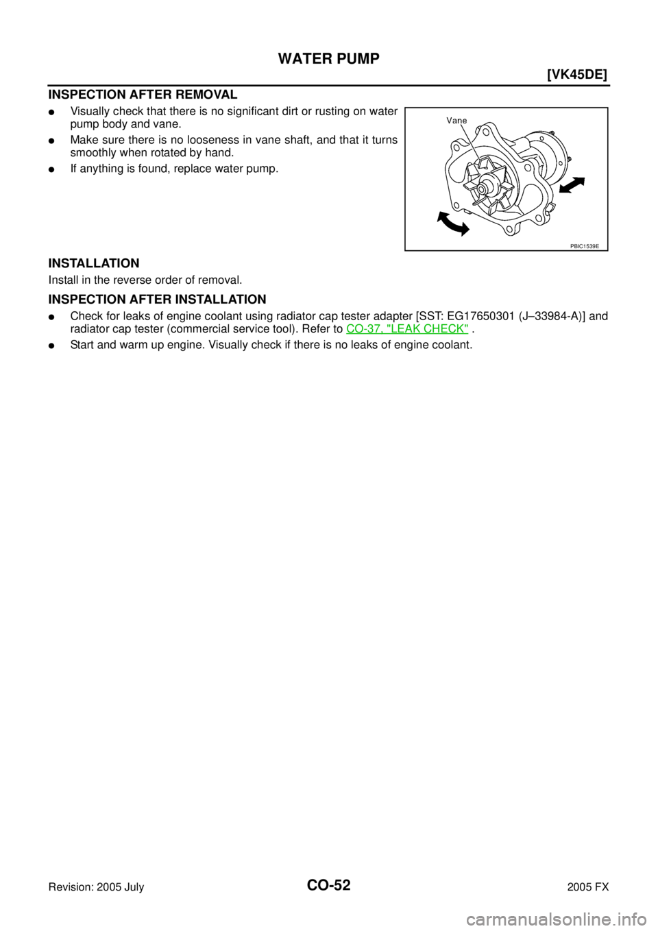
INSPECTION AFTER REMOVAL
�Visually check that there is no significant dirt or rusting on water
pump body and vane.
�Make sure there is no looseness in vane shaft, and that it turns
smoothly when rotated by hand.
�If anything is found, replace water pump.
INSTALLATION
Install in the reverse order of removal.
INSPECTION AFTER INSTALLATION
�Check for leaks of engine coolant using radiator cap tester adapter [SST: EG17650301 (J–33984-A)] and
radiator cap tester (commercial service tool). Refer to CO-37, "
LEAK CHECK" .
�Start and warm up engine. Visually check if there is no leaks of engine coolant.
PBIC1539E
Page 1258 of 4731
![INFINITI FX35 2005 Service Manual THERMOSTAT AND WATER CONTROL VALVE CO-53
[VK45DE]
C
D E
F
G H
I
J
K L
M A
CO
Revision: 2005 July 2005 FX
THERMOSTAT AND WATER CONTROL VALVEPFP:21200
Removal and InstallationABS006JP
REMOV](/manual-img/42/57020/w960_57020-1257.png "INFINITI FX35 2005 Service Manual THERMOSTAT AND WATER CONTROL VALVE CO-53
[VK45DE]
C
D E
F
G H
I
J
K L
M A
CO
Revision: 2005 July 2005 FX
THERMOSTAT AND WATER CONTROL VALVEPFP:21200
Removal and InstallationABS006JP
REMOV")
THERMOSTAT AND WATER CONTROL VALVE CO-53
[VK45DE]
C
D E
F
G H
I
J
K L
M A
CO
Revision: 2005 July 2005 FX
THERMOSTAT AND WATER CONTROL VALVEPFP:21200
Removal and InstallationABS006JP
REMOVAL
1. Drain engine coolant from drain plugs on radiator and both side of cylinder block. Refer to CO-37, "Chang-
ing Engine Coolant" and EM-246, "DISASSEMBLY" .
CAUTION:
�Perform this step when engine is cold.
�Do not spill engine coolant on drive belts.
2. Remove engine cover with power tool. Refer to EM-172, "
ENGINE ROOM COVER" .
3. Remove air duct (inlet). Refer to EM-176, "
AIR CLEANER AND AIR DUCT" .
4. Disconnect water suction hose from water inlet.
5. Remove water inlet and thermostat. CAUTION:
Do not disassemble thermostat.
6. Remove intake manifolds (upper and lower). Refer to EM-178, "
INTAKE MANIFOLD" .
1. Water connector 2. O-ring 3. Rubber ring
4. Heater hose 5. Water control valve 6. Water outlet
7. Gasket 8. O-ring 9. Water outlet pipe
10. Thermostat housing 11. Radiator cap 12. Radiator hose (upper)
13. Thermostat 14. Rubber ring 15. Water inlet
16. Water suction hose 17. Water suction pipe 18. Radiator hose (lower)
19. Gasket 20. O-ring 21. Heater pipe
22. Heater hose 23. Water hose 24. Water hose
PBIC1561E
Page 1260 of 4731
THERMOSTAT AND WATER CONTROL VALVE CO-55
[VK45DE]
C
D E
F
G H
I
J
K L
M A
CO
Revision: 2005 July 2005 FX
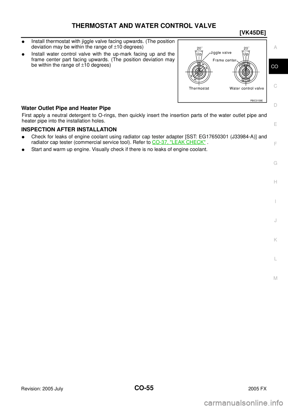
�Install thermostat with jiggle valve facing upwards. (The position
deviation may be within the range of ±10 degrees)
�Install water control valve with the up-mark facing up and the
frame center part facing upwards. (The position deviation may
be within the range of ±10 degrees)
Water Outlet Pipe and Heater Pipe
First apply a neutral detergent to O-rings, then quickly insert the insertion parts of the water outlet pipe and
heater pipe into the installation holes.
INSPECTION AFTER INSTALLATION
�Check for leaks of engine coolant using radiator cap tester adapter [SST: EG17650301 (J33984-A)] and
radiator cap tester (commercial service tool). Refer to CO-37, "
LEAK CHECK" .
�Start and warm up engine. Visually check if there is no leaks of engine coolant.
PBIC0158E
Page 1261 of 4731
CO-56
[VK45DE]
SERVICE DATA AND SPECIFICATIONS (SDS)
Revision: 2005 July 2005 FX
SERVICE DATA AND SPECIFICATIONS (SDS)PFP:00030
Standard and LimitABS006JQ
ENGINE COOLANT CAPACITY (APPROXIMATE)
Unit: (US qt, Imp qt)
RADIATOR
Unit: kPa (kg/cm2 , psi)
THERMOSTAT
WATER CONTROL VALVE
Engine coolant capacity (With reservoir tank at “MAX” level) 10.0 (10-5/8, 8-3/4)
Reservoir tank engine coolant capacity (at “MAX” level) 0.8 (7/8, 3/4)
Radiator cap relief pressure Standard 78 - 98 (0.8 - 1.0, 11 - 14)
Limit 59 (0.6, 9)
Leakage testing pressure 157 (1.6, 23)
Valve opening temperature 80 - 84 °C (176 - 183 °F)
Maximum valve lift More than 10 mm/ 95 °C (0.39 in/ 203 °F)
Valve closing temperature 77 °C (171 °F)
Valve opening temperature 93.5 - 96.5 °C (200 - 206 °F)
Maximum valve lift More than 8 mm/ 108 °C (0.315 in/ 226 °F)
Valve closing temperature 90 °C (194 °F)
Page 1420 of 4731
![INFINITI FX35 2005 Service Manual PREPARATION EC-27
[VQ35DE]
C
D E
F
G H
I
J
K L
M A
EC
Revision: 2005 July 2005 FX
PREPARATIONPFP:00002
Special Service ToolsABS006K2
The actual shapes of Kent-Moore tools may differ from](/manual-img/42/57020/w960_57020-1419.png "INFINITI FX35 2005 Service Manual PREPARATION EC-27
[VQ35DE]
C
D E
F
G H
I
J
K L
M A
EC
Revision: 2005 July 2005 FX
PREPARATIONPFP:00002
Special Service ToolsABS006K2
The actual shapes of Kent-Moore tools may differ from")
PREPARATION EC-27
[VQ35DE]
C
D E
F
G H
I
J
K L
M A
EC
Revision: 2005 July 2005 FX
PREPARATIONPFP:00002
Special Service ToolsABS006K2
The actual shapes of Kent-Moore tools may differ from those of special service tools illustrated here.
Tool number
(Kent-Moore No.)
Tool name Description
EG17650301
(J-33984-A)
Radiator cap tester
adapter Adapting radiator cap tester to radiator cap and
radiator filler neck
a: 28 (1.10) dia.
b: 31.4 (1.236) dia.
c: 41.3 (1.626) dia.
Unit: mm (in)
KV10117100
(J-36471-A)
Heated oxygen
sensor wrench Loosening or tightening heated oxygen sensor
with 22 mm (0.87 in) hexagon nut
KV10114400
(J-38365)
Heated oxygen
sensor wrench Loosening or tightening air fuel ratio (A/F) sensor
a: 22 mm (0.87 in)
(J-44321)
Fuel pressure gauge
kit Checking fuel pressure
(J-44321-6)
Fuel pressure adapter Connecting fuel pressure gauge to quick
connector type fuel lines.
(J-44626)
Air fuel ratio (A/F)
sensor wrench Loosening or tightening air fuel ratio (A/F) sensor
1
(J-45488)
Quick connector
release Remove fuel tube quick connectors in engine
room.
S-NT564
S-NT379
S-NT636
LEC642
LBIA0376E
LEM054
PBIC0198E
Page 1506 of 4731
![INFINITI FX35 2005 Service Manual TROUBLE DIAGNOSIS EC-113
[VQ35DE]
C
D E
F
G H
I
J
K L
M A
EC
Revision: 2005 July 2005 FX
1 - 6: The numbers refer to the order of inspection. Va l v e
mecha-
nism Timing chain
55555](/manual-img/42/57020/w960_57020-1505.png "INFINITI FX35 2005 Service Manual TROUBLE DIAGNOSIS EC-113
[VQ35DE]
C
D E
F
G H
I
J
K L
M A
EC
Revision: 2005 July 2005 FX
1 - 6: The numbers refer to the order of inspection. Va l v e
mecha-
nism Timing chain
55555")
TROUBLE DIAGNOSIS EC-113
[VQ35DE]
C
D E
F
G H
I
J
K L
M A
EC
Revision: 2005 July 2005 FX
1 - 6: The numbers refer to the order of inspection. Va l v e
mecha-
nism Timing chain
55555 55 5 EM-64
Camshaft
EM-84
Intake valve timing controlEM-64
Intake valve
3 EM-100
Exhaust valve
Exhaust Exhaust manifold/Tube/Muffler/ Gasket 55555 55 5 EM-26
,
EX-
3Three way catalyst
Lubrica-
tion Oil pan/Oil strainer/Oil pump/Oil
filter/Oil gallery/Oil cooler 55555 55 5 EM-30
,
LU-
17 , LU-10 ,
LU-14
Oil level (Low)/Filthy oil LU-7
Cooling
Radiator/Hose/Radiator filler cap
55555 55 45 CO-14,
CO-17
Thermostat 5 CO-26
Water pumpCO-22
Water galleryCO-28
Cooling fan 5EC-226
Coolant level (Low)/Contami-
nated coolant 5
CO-11
IVIS (Infiniti Vehicle Immobilizer System —
NATS) 11
EC-53 or
BL-213
SYMPTOM
Reference
page
HARD/NO START/RESTART (EXCP. HA)
ENGINE STALL
HESITATION/SURGING/FLAT SPOT
SPARK KNOCK/DETONATION
LACK OF POWER/POOR ACCELERATION
HIGH IDLE/LOW IDLE
ROUGH IDLE/HUNTING
IDLING VIBRATION
SLOW/NO RETURN TO IDLE
OVERHEATS/WATER TEMPERATURE HIGH
EXCESSIVE FUEL CONSUMPTION
EXCESSIVE OIL CONSUMPTION
BATTERY DEAD (UNDER CHARGE)
Warranty symptom code AA AB AC AD AE AF AG AH AJ AK AL AM HA
Page 1862 of 4731
![INFINITI FX35 2005 Service Manual DTC P1217 ENGINE OVER TEMPERATURE EC-469
[VQ35DE]
C
D E
F
G H
I
J
K L
M A
EC
Revision: 2005 July 2005 FX
CONSULT-II Reference Value in Data Monitor ModeABS006V9
Specification data are ref](/manual-img/42/57020/w960_57020-1861.png "INFINITI FX35 2005 Service Manual DTC P1217 ENGINE OVER TEMPERATURE EC-469
[VQ35DE]
C
D E
F
G H
I
J
K L
M A
EC
Revision: 2005 July 2005 FX
CONSULT-II Reference Value in Data Monitor ModeABS006V9
Specification data are ref")
DTC P1217 ENGINE OVER TEMPERATURE EC-469
[VQ35DE]
C
D E
F
G H
I
J
K L
M A
EC
Revision: 2005 July 2005 FX
CONSULT-II Reference Value in Data Monitor ModeABS006V9
Specification data are reference values.
On Board Diagnosis LogicABS006VA
If the cooling fan or another component in the cooling system malfunctions, engine coolant temperature will
rise.
When the engine coolant temperature reaches an abnormally high temperature condition, a malfunction is
indicated.
This self-diagnosis has the one trip detection logic.
CAUTION:
When a malfunction is indicated, be sure to replace the coolant. Refer to CO-11, "
Changing Engine
Coolant" . Also, replace the engine oil. Refer to LU-9, "Changing Engine Oil" .
1. Fill radiator with coolant up to specified level with a filling speed of 2 liters per minute. Be sure to use coolant with the proper mixture ratio. Refer to MA-13, "
Anti-Freeze Coolant Mixture Ratio" .
2. After refilling coolant, run engine to ensure that no water-flow noise is emitted.
Overall Function CheckABS006VB
Use this procedure to check the overall function of the cooling fan. During this check, a DTC might not be con-
firmed.
WARNING:
Never remove the radiator cap when the engine is hot. Serious burns could be caused by high pres-
sure fluid escaping from the radiator.
Wrap a thick cloth around cap. Carefully remove the cap by turning it a quarter turn to allow built-up
pressure to escape. Then turn the cap all the way off.
MONITOR ITEM CONDITION SPECIFICATION
AIR COND SIG
�Engine: After warming up, idle
the engine Air conditioner switch: OFF OFF
Air conditioner switch: ON
(Compressor operates.) ON
COOLING FAN
�Engine: After warming up, idle
the engine
�Air conditioner switch: OFF Engine coolant temperature is 94
°C
(201 °F) or less OFF
Engine coolant temperature is
between 95 °C (203 °F) and 99 °C
(210 °F) LOW
Engine coolant temperature is
between 100 °C (212 °F) and 104 °C
(219 °F) MID
Engine coolant temperature is 105 °C
(221 °F) or more HI
DTC No. Trouble diagnosis name DTC detecting condition Possible cause
P1217
1217 Engine over tempera-
ture (Overheat)
�Cooling fan does not operate properly (Over-
heat).
�Cooling fan system does not operate prop-
erly (Overheat).
�Engine coolant level was not added to the
system using the proper filling method.
�Engine coolant is not within the specified
range.
�Harness or connectors
(The cooling fan circuit is open or
shorted.)
�IPDM E/R
�Cooling fan
�Radiator hose
�Radiator
�Radiator cap
�Water pump
�Thermostat
For more information, refer to EC-478,
"Main 12 Causes of Overheating" .
![INFINITI FX35 2005 Service Manual CO-56
[VK45DE]
SERVICE DATA AND SPECIFICATIONS (SDS)
Revision: 2005 July 2005 FX
SERVICE DATA AND SPECIFICATIONS (SDS)PFP:00030
Standard and LimitABS006JQ
ENGINE COOLANT CAPACITY (APPROXIMATE)
Unit:](/manual-img/42/57020/w960_57020-1260.png "INFINITI FX35 2005 Service Manual CO-56
[VK45DE]
SERVICE DATA AND SPECIFICATIONS (SDS)
Revision: 2005 July 2005 FX
SERVICE DATA AND SPECIFICATIONS (SDS)PFP:00030
Standard and LimitABS006JQ
ENGINE COOLANT CAPACITY (APPROXIMATE)
Unit:")