Page 900 of 4731
REMOTE KEYLESS ENTRY SYSTEM BL-85
C
D E
F
G H
J
K L
M A
B
BL
Revision: 2005 July 2005 FX
6. Touch “MULTI REMOTE ENT”.
7. Touch “WORK SUPPORT”.
8. The items are shown on the figure can be set up.
�“REMO CONT ID CONFIR”
Use this mode to confirm if a key fob ID code is registered or
not.
�“REMO CONT ID REGIST”
Use this mode to register a key fob ID code.
NOTE:
Register the ID code when key fob or BCM is replaced, or
when additional key fob is required.
�“REMO CONT ID ERASUR”
Use this mode to erase a key fob ID code.
LIIA0194E
BCIA0031E
LIIA0207E
Page 901 of 4731
BL-86
REMOTE KEYLESS ENTRY SYSTEM
Revision: 2005 July 2005 FX
KEY FOB ID SET UP WITHOUT CONSULT-II
PIIA2839E
Page 902 of 4731

REMOTE KEYLESS ENTRY SYSTEM BL-87
C
D E
F
G H
J
K L
M A
B
BL
Revision: 2005 July 2005 FX
NOTE:
�If a key fob is lost, the ID code of the lost key fob must be erased to prevent unauthorized use. A specific
ID code can be erased with CONSULT-II. However, when the ID code of a lost key fob is not known, all
controller ID codes should be erased. After all ID codes are erased, the ID codes of all remaining and/or
new key fobs must be re-registered.
To erase all ID codes in memory, register one ID code (key fob) five times. After all ID codes are erased,
the ID codes of all remaining and/or new key fobs must be re-registered.
�When registering an additional key fob, the existing ID codes in memory may or may not be erased. If five
ID codes are stored in memory, when an additional code is registered, only the oldest code is erased. If
less than five ID codes are stored in memory, when an additional ID code is registered, the new ID code is
added and no ID codes are erased.
�If you need to activate more than two additional new key fobs, repeat the procedure “Additional ID code
entry” for each new key fob.
�Entry of maximum five ID codes is allowed. When more than five ID codes are entered, the oldest ID code
will be erased.
�Even if same ID code that is already in the memory is input, the same ID code can be entered. The code
is counted as an additional code.
Removal and Installation of Remote keyless Entry receiverAIS006A2
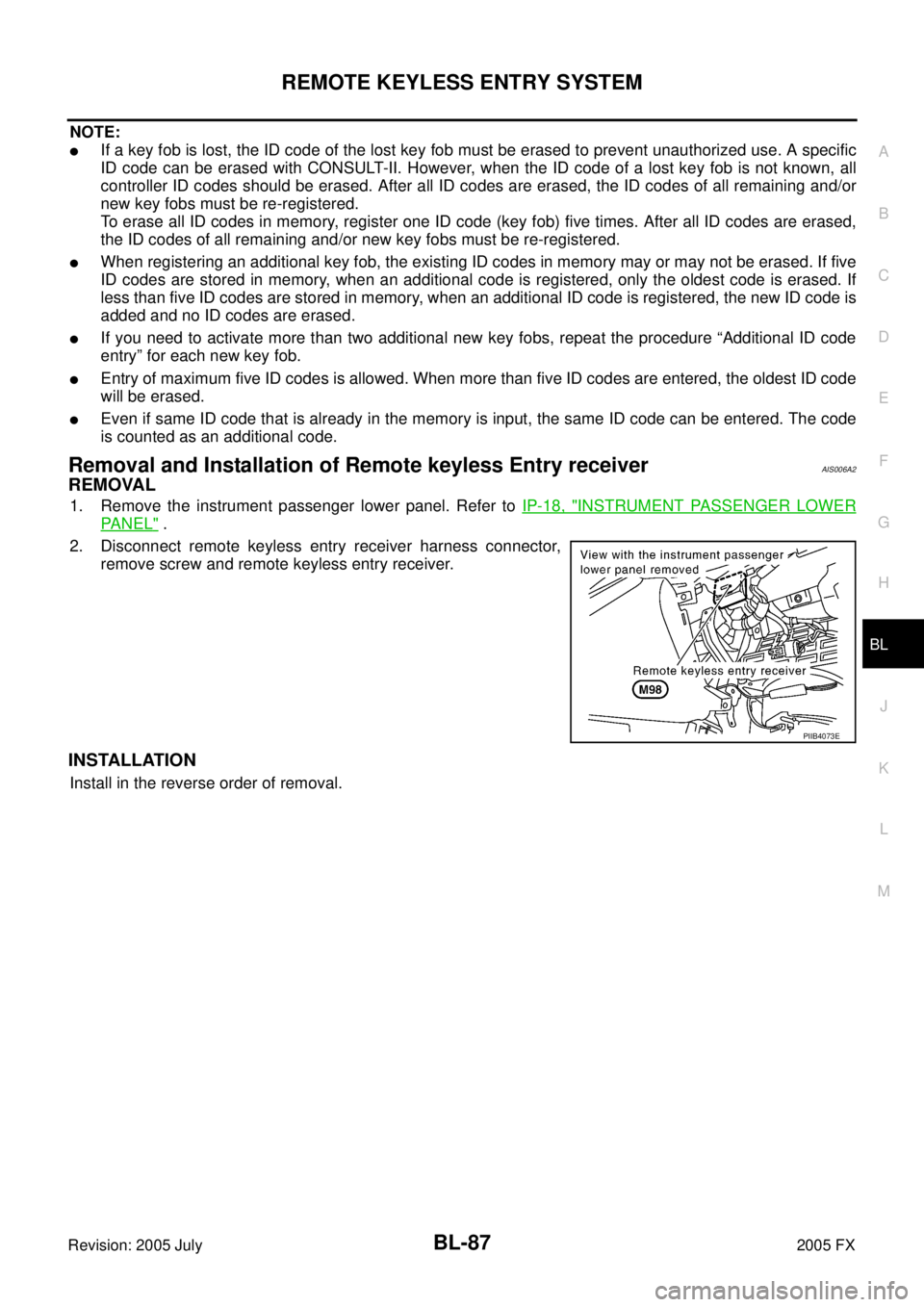
REMOVAL
1. Remove the instrument passenger lower panel. Refer to IP-18, "INSTRUMENT PASSENGER LOWER
PA N E L" .
2. Disconnect remote keyless entry receiver harness connector, remove screw and remote keyless entry receiver.
INSTALLATION
Install in the reverse order of removal.
PIIB4073E
Page 903 of 4731
BL-88
REMOTE KEYLESS ENTRY SYSTEM
Revision: 2005 July 2005 FX
Key Fob Battery ReplacementAIS004MU
PIIA4706E
Page 1005 of 4731

BL-190
VEHICLE SECURITY (THEFT WARNING) SYSTEM
Revision: 2005 July 2005 FX
�through back door closure motor terminal 8
�through body grounds B15 and B45.
VEHICLE SECURITY SYSTEM ALARM OPERATION
The vehicle security system is triggered by
�opening a door
�opening the back door
�opening the hood
�detection of battery disconnect and connect.
The vehicle security system will be triggered once the system is in armed phase,
When BCM receives a ground signal at terminals 12 (passenger side door), 13 (rear RH door), 58 (back door),
62 (driver side door), 63 (rear LH door), or receives a signal from the IPDM E/R (hood switch).
When the vehicle security system is triggered,
ground is supplied intermittently from IPDM E/R terminals 38 and 60.
When headlamp high relay (with built-in IPDM E/R) and horn relay are energized and then power is supplied
to headlamps (LH and RH) and horns (HIGH and LOW).
The headlamps flash and the horn sounds intermittently.
The alarm automatically turns off after 50 seconds, but will reactivate if the vehicle is tampered with again.
VEHICLE SECURITY SYSTEM DEACTIVATION
To deactivate the vehicle security system, a door or the back door must be unlocked with the key, key fob or
Intelligent Key.
When the key is used to unlock a door, BCM terminal 22 receives signal
�from terminal 14 of the power window main switch (door lock and unlock switch).
When the BCM receives either one of these signals or unlock signal from key cylinder switch, key fob or Intel-
ligent Key, the vehicle security system is deactivated. (Disarmed phase)
PANIC ALARM OPERATION
Remote keyless entry system may or may not operate vehicle security system (horn and headlamps) as
required.
When the remote keyless entry system is triggered, ground is supplied intermittently from IPDM E/R terminals
38 and 60.
When headlamp relay (which built-in IPDM E/R) and horn relay are energized and then power is supplied to
headlamps (LH and RH) and horns (HIGH and LOW).
The headlamp flashes and the horn sounds intermittently.
The alarm automatically turns off after 25 seconds or when BCM receives any signal from key fob or Intelligent
Key.
Page 1013 of 4731

BL-198
VEHICLE SECURITY (THEFT WARNING) SYSTEM
Revision: 2005 July 2005 FX
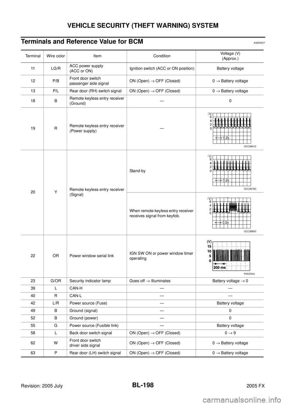
Terminals and Reference Value for BCMAIS004OY
Terminal Wire color Item Condition Voltage (V)
(Approx.)
11 L G / R ACC power supply
(ACC or ON) Ignition switch (ACC or ON position) Battery voltage
12 P/B Front door switch
passenger side signal ON (Open)
→ OFF (Closed) 0 → Battery voltage
13 P/L Rear door (RH) switch signal ON (Open) → OFF (Closed) 0 → Battery voltage
18 B Remote keyless entry receiver
(Ground) —0
19 R Remote keyless entry receiver
(Power supply) —
20 Y Remote keyless entry receiver
(Signal) Stand-by
When remote keyless entry receiver
receives signal from keyfob.
22 OR Power window serial link IGN SW ON or power window timer
operating
23 G/OR Security indicator lamp Goes off → Illuminates Battery voltage → 0
39 L CAN-H — —
40 R CAN-L — —
42 L/R Power source (Fuse) — Battery voltage
49 B Ground (signal) — 0
52 B Ground (power) — 0
55 G Power source (Fusible link) — Battery voltage
58 L Back door switch signal ON (Open) → OFF (Closed) 0 → 9
62 W Front door switch
driver side signal ON (Open)
→ OFF (Closed) 0 → Battery voltage
63 P Rear door (LH) switch signal ON (Open) → OFF (Closed) 0 → Battery voltage
OCC3881D
OCC3879D
OCC3880D
PIIA2344J
Page 1019 of 4731

BL-204
VEHICLE SECURITY (THEFT WARNING) SYSTEM
Revision: 2005 July 2005 FX
Trouble Diagnosis Symptom ChartAIS004P3
*1: Make sure the system is in the armed phase. Procedure
Diagnostic procedure Refer to page
Symptom
1 Vehicle security
system cannot be
set by ···· Door switch Diagnostic Procedure 1 (Check door, hood and back door switch)
BL-205
Lock / unlock switch Diagnostic Procedure 6 (Check door lock / unlock switch)BL-212
Door outside key Diagnostic Procedure 3 (Check door key cylinder switch)BL-212
Key fob Check remote keyless entry. BL-56
Intelligent Key Check Intelligent Key.BL-89
— If the above systems are “OK”, replace BCM.BCS-16
Security indicator does not turn “ON”. Diagnostic Procedure 2 (Check security indicator lamp)
BL-211If the above systems are “OK”, replace BCM.BCS-16
2 *1 Vehicle secu-
rity system does
not alarm when
···· Any door is opened. Diagnostic Procedure 1 (Check door, hood and back door switch)
BL-205If the above systems are “OK”, replace BCM.BCS-16
3 Vehicle security
alarm does not
activate. Horn alarm
Diagnostic Procedure 4 (Check vehicle security horn alarm)
BL-212
Check horn function. BL-83
If the above systems are “OK”, replace BCM.BCS-16
Head lamp alarm Diagnostic Procedure 5 (Check head lamp alarm)
BL-212If the above systems are “OK”, replace BCM.BCS-16
4 Vehicle security
system cannot be
canceled by ···· Door outside key
Diagnostic Procedure 3 (Check door key cylinder switch)
BL-212
If the above systems are “OK”, check power window main switch. EI-34
Key fob Check remote keyless entry function.
BL-57If the above systems are “OK”, replace BCM.BCS-16
Intelligent Key Check Intelligent Key
BL-91If the above systems are “OK”, replace BCM.BCS-16
Page 3348 of 4731

POWER WINDOW SYSTEM GW-71
C
D E
F
G H
J
K L
M A
B
GW
Revision: 2005 July 2005 FX
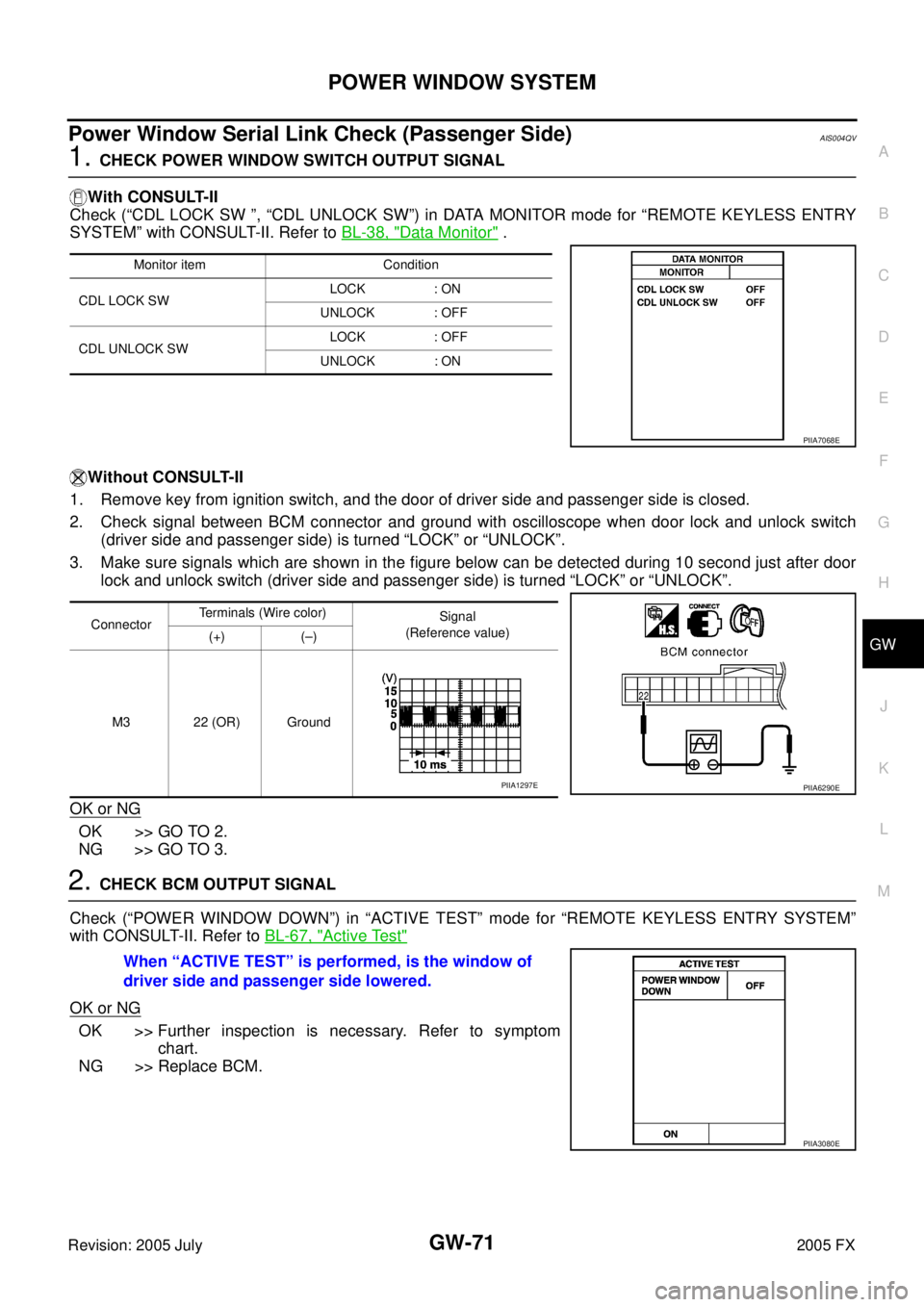
Power Window Serial Link Check (Passenger Side)AIS004QV
1. CHECK POWER WINDOW SWITCH OUTPUT SIGNAL
With CONSULT-II
Check (“CDL LOCK SW ”, “CDL UNLOCK SW”) in DATA MONITOR mode for “REMOTE KEYLESS ENTRY
SYSTEM” with CONSULT-II. Refer to BL-38, "
Data Monitor" .
Without CONSULT-II
1. Remove key from ignition switch, and the door of driver side and passenger side is closed.
2. Check signal between BCM connector and ground with oscilloscope when door lock and unlock switch (driver side and passenger side) is turned “LOCK” or “UNLOCK”.
3. Make sure signals which are shown in the figure below can be detected during 10 second just after door lock and unlock switch (driver side and passenger side) is turned “LOCK” or “UNLOCK”.
OK or NG
OK >> GO TO 2.
NG >> GO TO 3.
2. CHECK BCM OUTPUT SIGNAL
Check (“POWER WINDOW DOWN”) in “ACTIVE TEST” mode for “REMOTE KEYLESS ENTRY SYSTEM”
with CONSULT-II. Refer to BL-67, "
Active Test"
OK or NG
OK >> Further inspection is necessary. Refer to symptom
chart.
NG >> Replace BCM.
Monitor item Condition
CDL LOCK SW LOCK : ON
UNLOCK : OFF
CDL UNLOCK SW LOCK : OFF
UNLOCK : ON
PIIA7068E
Connector Terminals (Wire color)
Signal
(Reference value)
(+) (–)
M3 22 (OR) Ground
PIIA6290EPIIA1297E
When “ACTIVE TEST” is performed, is the window of
driver side and passenger side lowered.
PIIA3080E