Page 4202 of 4731

IPDM E/R (INTELLIGENT POWER DISTRIBUTION MODULE ENGINE ROOM) PG-25
C
D E
F
G H
I
J
L
M A
B
PG
Revision: 2005 July 2005 FX
Concept of Auto Active Test
�IPDM E/R actuates auto active test mode when it receives door switch signal from BCM via CAN commu-
nication line. Therefore, when auto active test mode is activated successfully, CAN communication
between IPDM E/R and BCM is normal.
�If any of systems controlled by IPDM E/R cannot be operated, possible cause can be easily diagnosed
using auto active test.
Diagnosis chart in auto active test mode
Symptom Inspection contents Possible cause
Any of front wipers, tail
and parking lamps, front
fog lamps, and head
lamps (Hi, Lo) do not
operate. Perform auto active
test. Does system in
question operate? YES
�BCM signal input system malfunction
NO
�Lamp/wiper motor malfunction
�Lamp/wiper motor ground circuit malfunction
�Harness/connector malfunction between IPDM E/R and system in ques-
tion
�IPDM E/R (integrated relay) malfunction
Rear window defogger
does not operate. Perform auto active
test. Does rear win-
dow defogger oper-
ate? YES
�BCM signal input circuit malfunction
NO
�Rear window defogger relay malfunction
�Harness/connector malfunction between IPDM E/R and rear window
defogger relay.
�Open circuit of rear window defogger
�IPDM E/R malfunction
A/C compressor does
not operate. Perform auto active
test. Does magnetic
clutch operate? YES
�BCM signal input circuit malfunction
�CAN communication signal between BCM and ECM.
�CAN communication signal between ECM and IPDM E/R
NO
�Magnetic clutch malfunction
�Harness/connector malfunction between IPDM E/R and magnetic clutch
�IPDM E/R (integrated relay) malfunction
Cooling fan does not
operate. Perform auto active
test. Does cooling
fan operate? YES
�ECM signal input circuit
�CAN communication signal between ECM and IPDM E/R
NO
�Cooling fan motor malfunction
�Harness/connector malfunction between IPDM E/R and cooling fan motor
�IPDM E/R (integrated relay) malfunction
Oil pressure warning
lamp does not operate. Perform auto active
test. Does oil pres-
sure warning lamp
blink? YES
�Harness/connector malfunction between IPDM E/R and oil pressure
switch
�Oil pressure switch malfunction
�IPDM E/R malfunction
NO
�CAN communication signal between BCM and Unified Meter and A/C Amp
�Combination meter
Page 4244 of 4731

HARNESS PG-67
C
D E
F
G H
I
J
L
M A
B
PG
Revision: 2005 July 2005 FX
Wiring Diagram Codes (Cell Codes) AKS007X0
Use the chart below to find out what each wiring diagram code stands for.
Refer to the wiring diagram code in the alphabetical index to find the location (page number) of each wiring
diagram.
Code Section Wiring Diagram Name
A/C ATC Air Conditioner
APPS1 EC Accelerator Pedal Position Sensor
APPS2 EC Accelerator Pedal Position Sensor
APPS3 EC Accelerator Pedal Position Sensor
ASC/BS EC Automatic Speed Control Device (ASCD) Brake Switch
ASC/SW EC Automatic Speed Control Device (ASCD) Steering Switch
ASCBOF EC Automatic Speed Control Device (ASCD) Brake Switch
ASCIND EC Automatic Speed Control Device (ASCD) Indicator
AT/IND DI A/T Indicator Lamp
AUDIO AV Audio
AUT/DP SE Automatic Drive Positioner
AUTO/L LT Automatic Light System
AWD TF AWD Control System
B/CLOS BL Back Door Closure System
BACK/L LT Back-Up Lamp
BRK/SW EC Brake Switch
CAN AT CAN Communication Line
CAN EC CAN Communication Line
CAN LAN CAN System
CHARGE SC Charging System
CHIME DI Warning Chime
CIGAR WW Cigarette Lighter
CLOCK DI Clock
COMBSW LT Combination Switch
COMM AV Audio Visual Communication Line
COMPAS DI Compass
COOL/F EC Cooling Fan Control
D/LOCK BL Power Door Lock
DEF GW Rear Window Defogger
DTRL LT Headlamp - With Daytime Light System
ECM/PW EC ECM Power Supply for Back-Up
ECTS EC Engine Coolant Temperature Sensor
ETC1 EC Electric Throttle Control Function
ETC2 EC Electric Throttle Control Motor Relay
ETC3 EC Electric Throttle Control Motor
F/FOG LT Front Fog Lamp
F/PUMP EC Fuel Pump
FTS AT A/T Fluid Temperature Sensor Circuit
FTTS EC Fuel Tank Temperature Sensor
FUELB1 EC Fuel Injection System Function (Bank 1)
FUELB2 EC Fuel Injection System Function (Bank 2)
Page 4647 of 4731

TF-14
TROUBLE DIAGNOSIS
Revision: 2005 July 2005 FX
TROUBLE DIAGNOSISPFP:00004
Fail-Safe FunctionADS000S1
�If any malfunction occurs in AWD electrical system, and control unit detects the malfunction, AWD warn-
ing lamp on combination meter turns ON to indicate system malfunction.
�When AWD warning lamp is ON, vehicle changes to rear-wheel drive or shifting driving force-AWD (Front-
wheels still have some driving torque).
How to Perform Trouble DiagnosisADS000S2
BASIC CONCEPT
�To perform trouble diagnosis, it is the most important to have understanding about vehicle systems (con-
trol and mechanism) thoroughly.
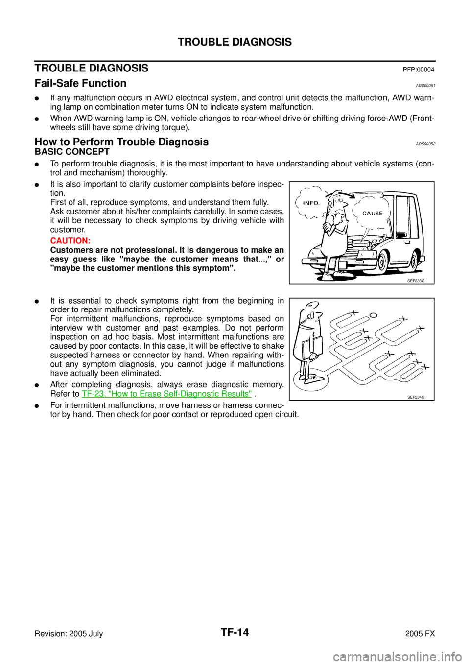
�It is also important to clarify customer complaints before inspec-
tion.
First of all, reproduce symptoms, and understand them fully.
Ask customer about his/her complaints carefully. In some cases,
it will be necessary to check symptoms by driving vehicle with
customer.
CAUTION:
Customers are not professional. It is dangerous to make an
easy guess like "maybe the customer means that...," or
"maybe the customer mentions this symptom".
�It is essential to check symptoms right from the beginning in
order to repair malfunctions completely.
For intermittent malfunctions, reproduce symptoms based on
interview with customer and past examples. Do not perform
inspection on ad hoc basis. Most intermittent malfunctions are
caused by poor contacts. In this case, it will be effective to shake
suspected harness or connector by hand. When repairing with-
out any symptom diagnosis, you cannot judge if malfunctions
have actually been eliminated.
�After completing diagnosis, always erase diagnostic memory.
Refer to TF-23, "
How to Erase Self-Diagnostic Results" .
�For intermittent malfunctions, move harness or harness connec-
tor by hand. Then check for poor contact or reproduced open circuit.
SEF233G
SEF234G
Page 4712 of 4731

TROUBLE DIAGNOSES WT-19
C
D
F
G H
I
J
K L
M A
B
WT
Revision: 2005 July 2005 FX
Self-DiagnosisAES000Z7
DESCRIPTION
During driving, the low tire pressure warning system receives the signal transmitted from the transmitter
installed in each wheel, and gives alarms when the tire pressure becomes low. The control unit (BCM) of this
system has pressure judgement and trouble diagnosis functions.
FUNCTION
When the low tire pressure warning system detects low inflation pressure or another unusual symptom, the
warning lamps in the combination meter comes on. To start the self-diagnostic results mode, ground terminal
of the tire pressure warning check connector. The malfunction location is indicated by the warning lamp flash-
ing and the buzzer sounds.
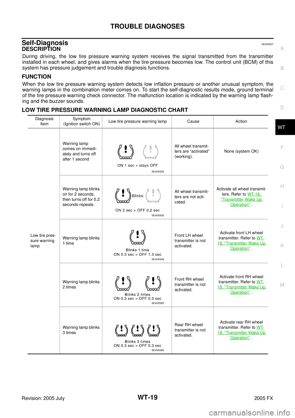
LOW TIRE PRESSURE WARNING LAMP DIAGNOSTIC CHART
Diagnosis
Item Symptom
(Ignition switch ON) Low tire pressure warning lamp Cause Action
Low tire pres-
sure warning
lamp Warning lamp
comes on immedi-
ately and turns off
after 1 second All wheel transmit-
ters are “activated”
(working). None (system OK)
Warning lamp blinks
on for 2 seconds,
then turns off for 0.2
seconds-repeats All wheel transmit-
ters are not acti-
vated. Activate all wheel transmit-
ters. Refer to WT-18,
"Transmitter Wake Up
Operation" .
Warning lamp blinks
1 time Front LH wheel
transmitter is not
activated. Activate front LH wheel
transmitter. Refer to WT-
18, "Transmitter Wake Up
Operation" .
Warning lamp blinks
2 times Front RH wheel
transmitter is not
activated. Activate front RH wheel
transmitter. Refer to WT-
18, "Transmitter Wake Up
Operation" .
Warning lamp blinks
3 times Rear RH wheel
transmitter is not
activated. Activate rear RH wheel
transmitter. Refer to WT-
18, "Transmitter Wake Up
Operation" .
SEIA0592E
SEIA0593E
SEIA0594E
SEIA0595E
SEIA0596E