Page 2875 of 4731
![INFINITI FX35 2005 Service Manual EM-40
[VQ35DE]
OIL PAN AND OIL STRAINER
Revision: 2005 July 2005 FX
d. Apply a continuous bead of liquid gasket with the tube presser
[SST: WS39930000 ( — )] to the cylinder block mating sur-
face](/manual-img/42/57020/w960_57020-2874.png "INFINITI FX35 2005 Service Manual EM-40
[VQ35DE]
OIL PAN AND OIL STRAINER
Revision: 2005 July 2005 FX
d. Apply a continuous bead of liquid gasket with the tube presser
[SST: WS39930000 ( — )] to the cylinder block mating sur-
face")
EM-40
[VQ35DE]
OIL PAN AND OIL STRAINER
Revision: 2005 July 2005 FX
d. Apply a continuous bead of liquid gasket with the tube presser
[SST: WS39930000 ( — )] to the cylinder block mating sur-
face of oil pan (upper) to a limited portion as shown in the figure.
Use Genuine RTV Silicone Sealant or equivalent. Refer to
GI-48, "
RECOMMENDED CHEMICAL PRODUCTS AND
SEALANTS" .
CAUTION:
�For bolt holes with marks (5 locations), apply liquid
gasket outside the holes.
�Apply a bead of 4.5 to 5.5 mm (0.177 to 0.217 in) in diame-
ter to area “A”.
�Attaching should be done within 5 minutes after coating.
e. Install oil pan (upper). CAUTION:
Install avoiding misalignment of both oil pan gasket and O-rings.
�Tighten mounting bolts in numerical order as shown in the fig-
ure.
�There are two types of mounting bolts. Refer to the following
for locating bolts.
f. Tighten transmission joint bolts. Refer to AT- 2 7 0 , "
TRANSMISSION ASSEMBLY" .
3. Install oil strainer to oil pump.
4. Install oil pan (lower) as follows:
a. Use scraper to remove old liquid gasket from mating surfaces.
�Also remove old liquid gasket from mating surface of oil pan
(upper).
�Remove old liquid gasket from the bolt holes and thread.
CAUTION:
Do not scratch or damage the mating surfaces when clean-
ing off old liquid gasket. M8
× 100 mm (3.94 in) : 5, 7, 8, 11
M8 × 25 mm (0.98 in) : Except the above
PBIC2300E
PBIC0783E
SEM958F
Page 2890 of 4731
![INFINITI FX35 2005 Service Manual FRONT TIMING CHAIN CASE EM-55
[VQ35DE]
C
D E
F
G H
I
J
K L
M A
EM
Revision: 2005 July 2005 FX
16. Remove collared O-ring from front timing chain case (left and
right side).
17. Remove r](/manual-img/42/57020/w960_57020-2889.png "INFINITI FX35 2005 Service Manual FRONT TIMING CHAIN CASE EM-55
[VQ35DE]
C
D E
F
G H
I
J
K L
M A
EM
Revision: 2005 July 2005 FX
16. Remove collared O-ring from front timing chain case (left and
right side).
17. Remove r")
FRONT TIMING CHAIN CASE EM-55
[VQ35DE]
C
D E
F
G H
I
J
K L
M A
EM
Revision: 2005 July 2005 FX
16. Remove collared O-ring from front timing chain case (left and
right side).
17. Remove rocker covers (right and left banks). Refer to EM-51, "
ROCKER COVER" .
NOTE:
When only timing chain (primary) is removed, rocker cover does not need to be removed.
18. Obtain No. 1 cylinder at TDC of its compression stroke as follows:
NOTE:
When timing chain is not removed/installed, this step is not required.
a. Rotate crankshaft pulley clockwise to align timing mark (grooved line without color) with timing indicator.
b. Make sure that intake and exhaust cam noses on No. 1 cylinder (engine front side of right bank) are located as shown in the fig-
ure.
�If not, turn crankshaft one revolution (360 degrees) and align
as shown in the figure.
NOTE:
When only timing chain (primary) is removed, rocker cover does
not need to be removed. To make sure that No. 1 cylinder is at
its compression TDC, remove front timing chain case first. Then
check mating marks on camshaft sprockets. Refer to EM-73,
"INSTALLATION" .
19. Remove crankshaft pulley as follows:
a. Remove rear cover plate (2WD) or starter motor (AWD) and set ring gear stopper [SST] as shown in the figure. Refer to SC-10,
"STARTING SYSTEM" .
PBIC2631E
KBIA1717J
SEM418G
PBIC1098E
Page 2897 of 4731
![INFINITI FX35 2005 Service Manual EM-62
[VQ35DE]
FRONT TIMING CHAIN CASE
Revision: 2005 July 2005 FX
c. Install new collared O-rings in front timing chain case oil hole
(left and right sides).
d. Being careful not to move seal ring](/manual-img/42/57020/w960_57020-2896.png "INFINITI FX35 2005 Service Manual EM-62
[VQ35DE]
FRONT TIMING CHAIN CASE
Revision: 2005 July 2005 FX
c. Install new collared O-rings in front timing chain case oil hole
(left and right sides).
d. Being careful not to move seal ring")
EM-62
[VQ35DE]
FRONT TIMING CHAIN CASE
Revision: 2005 July 2005 FX
c. Install new collared O-rings in front timing chain case oil hole
(left and right sides).
d. Being careful not to move seal ring from the installation groove, align dowel pins on front timing chain case with the holes to install intake valve timing control covers.
e. Tighten mounting bolts in numerical order as shown in the fig- ure.
9. Install crankshaft pulley as follows:
a. Fix crankshaft using the ring gear stopper [SST: KV10117700 (J44716)].
b. Install crankshaft pulley, taking care not to damage front oil seal.
�When press-fitting crankshaft pulley with plastic hammer, tap on its center portion (not circumference).
c. Tighten crankshaft pulley bolt.
d. Put a paint mark on crankshaft pulley aligning with angle mark on crankshaft pulley bolt. Then, further retighten bolt by 60 to 65
degrees [Target: 60 degrees (equivalent to one graduation)].
10. Rotate crankshaft pulley in normal direction (clockwise when viewed from front) to confirm it turns smoothly.
11. For the following operations, perform steps in the reverse order of removal. NOTE:
If hydraulic pressure inside chain tensioner drops after removal/installation, slack in the guide may gener-
ate a pounding noise during and just after engine start. However, this is normal. Noise will stop after
hydraulic pressure rises.
PBIC2631E
PBIC0918E
: 44.1 N·m (4.5 kg-m, 33 ft-lb)
SEM751G
Page 2901 of 4731
![INFINITI FX35 2005 Service Manual EM-66
[VQ35DE]
TIMING CHAIN
Revision: 2005 July 2005 FX
�Loosen mounting bolts in reverse order as shown in the fig-
ure.
�U s e t h e s e a l c u t t e r [ S S T: K V 1 0 1111 0 0 ( J 3 7 2 2](/manual-img/42/57020/w960_57020-2900.png "INFINITI FX35 2005 Service Manual EM-66
[VQ35DE]
TIMING CHAIN
Revision: 2005 July 2005 FX
�Loosen mounting bolts in reverse order as shown in the fig-
ure.
�U s e t h e s e a l c u t t e r [ S S T: K V 1 0 1111 0 0 ( J 3 7 2 2")
EM-66
[VQ35DE]
TIMING CHAIN
Revision: 2005 July 2005 FX
�Loosen mounting bolts in reverse order as shown in the fig-
ure.
�U s e t h e s e a l c u t t e r [ S S T: K V 1 0 1111 0 0 ( J 3 7 2 2 8 ) ] t o c u t l i q u i d
gasket for removal.
CAUTION:
Shaft is internally jointed with camshaft sprocket (INT) cen-
ter hole. When removing, keep it horizontal until it is com-
pletely disconnected.
19. Remove collared O-ring from front timing chain case (left and right side).
20. Remove rocker covers (right and left). Refer to EM-51, "
ROCKER COVER" .
21. Remove oil pans (lower and upper). Refer to EM-30, "
OIL PAN AND OIL STRAINER" .
22. Obtain No. 1 cylinder at TDC of its compression stroke as follows:
a. Rotate crankshaft pulley clockwise to align timing mark (grooved line without color) with timing indicator.
b. Make sure that intake and exhaust cam noses on No. 1 cylinder (engine front side of right bank) are located as shown in the fig-
ure.
�If not, turn crankshaft one revolution (360 degrees) and align
as shown in the figure.
23. Remove crankshaft pulley as follows:
SEM728G
PBIC2631E
KBIA1717J
SEM418G
Page 2906 of 4731
TIMING CHAIN EM-71
[VQ35DE]
C
D E
F
G H
I
J
K L
M A
EM
Revision: 2005 July 2005 FX
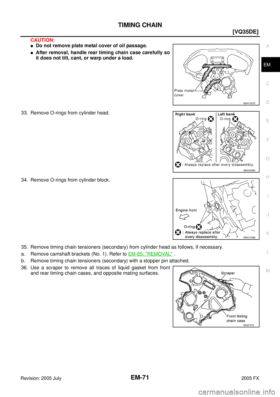
CAUTION:
�Do not remove plate metal cover of oil passage.
�After removal, handle rear timing chain case carefully so
it does not tilt, cant, or warp under a load.
33. Remove O-rings from cylinder head.
34. Remove O-rings from cylinder block.
35. Remove timing chain tensioners (secondary) from cylinder head as follows, if necessary.
a. Remove camshaft brackets (No. 1). Refer to EM-85, "
REMOVAL" .
b. Remove timing chain tensioners (secondary) with a stopper pin attached.
36. Use a scraper to remove all traces of liquid gasket from front and rear timing chain cases, and opposite mating surfaces.
KBIA1307E
SBIA0496E
PBIC0788E
SEM737G
Page 2908 of 4731
TIMING CHAIN EM-73
[VQ35DE]
C
D E
F
G H
I
J
K L
M A
EM
Revision: 2005 July 2005 FX
INSTALLATION
NOTE:
The below figure shows the relationship between the mating mark on each timing chain and that on the corre-
sponding sprocket, with the components installed.
1. Install timing chain tensioners (secondary) to cylinder head as follows if removed. Refer to EM-89,
"INSTALLATION" .
a. Install timing chain tensioners (secondary) with a stopper pin attached and new O-rings.
b. Install camshaft brackets (No. 1). Refer to EM-89, "
INSTALLATION" .
2. Install rear timing chain case as follows:
a. Install new O-rings onto cylinder block.
PBIC1792E
PBIC0788E
Page 2909 of 4731
EM-74
[VQ35DE]
TIMING CHAIN
Revision: 2005 July 2005 FX
b. Install new O-rings to cylinder head.
c. Apply liquid gasket with the tube presser [SST: WS39930000 ( — )] to rear timing chain case back side
as shown in the figure.
Use Genuine RTV Silicone Sealant or equivalent. Refer to GI-48, "
RECOMMENDED CHEMICAL
PRODUCTS AND SEALANTS" .
CAUTION:
�For “A” in the figure, completely wipe out liquid gasket extended on a portion touching at
engine coolant.
�Apply liquid gasket on installation position of water pump and cylinder head very completely.
d. Align rear timing chain case and water pump assembly with dowel pins (right and left) on cylinder block and install rear timing chain case.
�Make sure O-rings stay in place during installation to cylinder block and cylinder head.
SBIA0496E
PBIC2680E
Page 2910 of 4731
![INFINITI FX35 2005 Service Manual TIMING CHAIN EM-75
[VQ35DE]
C
D E
F
G H
I
J
K L
M A
EM
Revision: 2005 July 2005 FX
e. Tighten mounting bolts in numerical order as shown in the fig-
ure.
�There are two type mounting bol](/manual-img/42/57020/w960_57020-2909.png "INFINITI FX35 2005 Service Manual TIMING CHAIN EM-75
[VQ35DE]
C
D E
F
G H
I
J
K L
M A
EM
Revision: 2005 July 2005 FX
e. Tighten mounting bolts in numerical order as shown in the fig-
ure.
�There are two type mounting bol")
TIMING CHAIN EM-75
[VQ35DE]
C
D E
F
G H
I
J
K L
M A
EM
Revision: 2005 July 2005 FX
e. Tighten mounting bolts in numerical order as shown in the fig-
ure.
�There are two type mounting bolts. Refer to the following for
locating bolts.
f. After all bolts are tightened, retighten them to the specified torque in numerical order shown in the figure.
�If liquid gasket protrudes, wipe it off immediately.
g. After installing rear timing chain case, check the surface height difference between the following parts on the oil pan (upper)
mounting surface.
�If not within the standard, repeat the installation procedure.
3. Install water pump with new O-rings. Refer to CO-22, "
WATER PUMP" .
4. Make sure that dowel pin hole, dowel pin and crankshaft key are located as shown in the figure. (No. 1 cylinder at compression
TDC)
NOTE:
Though camshaft does not stop at the position as shown in the
figure, for the placement of cam nose, it is generally accepted
camshaft is placed for the same direction of the figure.
CAUTION:
Hole on small dia. side must be used for intake side dowel pin hole. Do not misidentify (ignore big
dia. side).
5. Install timing chains (secondary) and camshaft sprockets as follows: CAUTION:
Mating marks between timing chain and sprockets slip easily. Confirm all mating mark positions
repeatedly during the installation process. Bolt length: Bolt position
20 mm (0.79 in) : 1, 2, 3, 6, 7, 8, 9, 10
16 mm (0.63 in) : Except the above
: 12.7 N·m (1.3 kg-m, 9 ft-lb)
Standard Rear timing chain case to cylinder block: –0.24 to 0.14 mm (–0.009 to 0.006 in)
SEM735G
SEM943G
Camshaft dowel pin hole (intake side): At cylinder head upper face side in each bank.
Camshaft dowel pin (exhaust side) : At cylinder head upper face side in each bank.
Crankshaft key : At cylinder head side of right bank.
KBIA1073E
![INFINITI FX35 2005 Service Manual TIMING CHAIN EM-73
[VQ35DE]
C
D E
F
G H
I
J
K L
M A
EM
Revision: 2005 July 2005 FX
INSTALLATION
NOTE:
The below figure shows the relationship between the mating mark on each timing chain](/manual-img/42/57020/w960_57020-2907.png "INFINITI FX35 2005 Service Manual TIMING CHAIN EM-73
[VQ35DE]
C
D E
F
G H
I
J
K L
M A
EM
Revision: 2005 July 2005 FX
INSTALLATION
NOTE:
The below figure shows the relationship between the mating mark on each timing chain")
![INFINITI FX35 2005 Service Manual EM-74
[VQ35DE]
TIMING CHAIN
Revision: 2005 July 2005 FX
b. Install new O-rings to cylinder head.
c. Apply liquid gasket with the tube presser [SST: WS39930000 ( — )] to rear timing chain case back](/manual-img/42/57020/w960_57020-2908.png "INFINITI FX35 2005 Service Manual EM-74
[VQ35DE]
TIMING CHAIN
Revision: 2005 July 2005 FX
b. Install new O-rings to cylinder head.
c. Apply liquid gasket with the tube presser [SST: WS39930000 ( — )] to rear timing chain case back")