Page 4163 of 4731
MA-36
CHASSIS AND BODY MAINTENANCE
Revision: 2005 July 2005 FX
Checking Disc BrakeALS000FT
ROTOR
Check condition, wear, and damage.
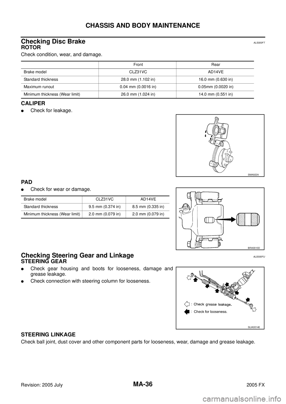
CALIPER
�Check for leakage.
PA D
�Check for wear or damage.
Checking Steering Gear and LinkageALS000FU
STEERING GEAR
�Check gear housing and boots for looseness, damage and
grease leakage.
�Check connection with steering column for looseness.
STEERING LINKAGE
Check ball joint, dust cover and other component parts for looseness, wear, damage and grease leakage.
Front Rear
Brake model CLZ31VC AD14VE
Standard thickness 28.0 mm (1.102 in) 16.0 mm (0.630 in)
Maximum runout 0.04 mm (0.0016 in) 0.05mm (0.0020 in)
Minimum thickness (Wear limit) 26.0 mm (1.024 in) 14.0 mm (0.551 in)
SMA922A
Brake model CLZ31VC AD14VE
Standard thickness 9.5 mm (0.374 in) 8.5 mm (0.335 in)
Minimum thickness (Wear limit) 2.0 mm (0.079 in) 2.0 mm (0.079 in)
BRA0010D
SLIA0014E
Page 4164 of 4731

CHASSIS AND BODY MAINTENANCE MA-37
C
D E
F
G H
I
J
K
M A
B
MA
Revision: 2005 July 2005 FX
Checking Power Steering Fluid and LinesALS000FV
Check fluid level in reservoir tank with engine off.
Use “HOT” range at fluid temperatures of 50 to 80 °C (122 to 176 °F)
or “COLD” range at fluid temperatures of 0 to 30 °C (32 to 86 °F).
CAUTION:
�Do not overfill.
�Recommended fluid is Genuine NISSAN PSF or equivalent.
Refer to MA-12, "
RECOMMENDED FLUIDS AND LUBRI-
CANTS"
�Check lines for improper attachment, leaks, cracks, dam-
age, loose connections, chafing and deterioration.
�Check rack boots for accumulation of power steering fluid.
Axle and Suspension PartsALS000FW
Check front and rear axle and suspension parts for excessive play,
cracks, wear or other damage.
�Shake each wheel to check for excessive play.
�Check wheel bearings for smooth operation.
�Check axle and suspension nuts and bolts for looseness.
�Check strut (shock absorber) for oil leakage or other damage.
�Check suspension ball joint for grease leakage and ball joint
dust cover for cracks or other damage.
SST850C
SST851C
SMA525A
SFA392B
Page 4280 of 4731
AGS000GQ
The actual shapes of Kent-Moore tools may differ from thos")
PREPARATION PS-5
C
D E
F
H I
J
K L
M A
B
PS
Revision: 2005 July 2005 FX
PREPARATIONPFP:00002
Special Service Tools (SST)AGS000GQ
The actual shapes of Kent-Moore tools may differ from those of special service tools illustrated here.
Tool number
(Kent-Moore No.)
Tool name Description
ST3127 S000
(See J25765-A)
Preload gauge
1. GG9103000
(J25765-A)
Torque wrench
2. HT62940000
( — )
Socket adapter
3. HT62900000
( — )
Socket adapter Inspecting of sliding torque, steering
torque, and rotating torque for ball joint
HT72520000
(J25730-A)
Ball joint remover
a: 33 mm (1.3 in)
b: 50 mm (1.97 in)
r: 11.5 mm (0.45 in) Removing steering outer socket
KV4810 5400
(J-46213)
Rear cover wrench
a: 21.6 mm (0.85 in)
b: 34.9 mm (1.37 in) Removing rear cover
KV48104400
( — )
Teflon ring correcting tool
a: 50 mm (1.97 in) dia.
b: 36 mm (1.42 in) dia.
c: 100 mm (3.94 in) Installing of rack Teflon ring
KV48103400
( — )
Torque adapter Inspecting rotating torque
S-NT541
NT546
SGIA0516E
S-NT550
ZZA0824D
Page 4282 of 4731
 TROUBLESHOOTING PS-7
C
D E
F
H I
J
K L
M A
B
PS
Revision: 2005 July 2005 FX
NOISE, VIBRATION AND HARSHNESS (NVH) TROUBLESHOOTINGPFP:00003
NVH Troubles")
NOISE, VIBRATION AND HARSHNESS (NVH) TROUBLESHOOTING PS-7
C
D E
F
H I
J
K L
M A
B
PS
Revision: 2005 July 2005 FX
NOISE, VIBRATION AND HARSHNESS (NVH) TROUBLESHOOTINGPFP:00003
NVH Troubleshooting ChartAGS000GS
Use chart below to help you find the cause of the symptom. If necessary, repair or replace these parts.
×: Applicable Reference page
PS-8PS-8PS-25PS-25PS-25PS-8PS-10PS-10
EM-15
,
EM-173PS-10PS-12PS-19PS-12PS-12PS-19
NVH in PR section
NVH in RFD section
NVH in FAX, RAX, FSU, RSU section NVH in WT section
NVH in WT section
NVH in FAX section
NVH in BR section
Possible cause and suspected parts
Fluid level
Air in hydraulic system
Outer socket ball joint swinging force
Outer socket ball joint rotating torque
Outer socket ball joint end play
Steering fluid leakage
Steering wheel play
Steering gear rack sliding force
Drive belt looseness
Improper steering wheel
Improper installation or looseness of tilt lock lever
Mounting rubber deterioration
Steering column deformation or damage
Improper installation or looseness of steering column
Steering linkage looseness
PROPELLER SHAFT
DIFFERENTIAL
AXLE and SUSPENSION
TIRES
ROAD WHEEL
DRIVE SHAFT
BRAKES
Symptom STEERING Noise
× × ××××× × × ×××××× ×
Shake ××× × ×××× ×
Vibration ××××× × ×× ×
Shimmy ××× × ××× ×
Judder ××××××
Page 4294 of 4731

POWER STEERING GEAR AND LINKAGE PS-19
C
D E
F
H I
J
K L
M A
B
PS
Revision: 2005 July 2005 FX
POWER STEERING GEAR AND LINKAGEPFP:49001
Removal and InstallationAGS000H0
CAUTION:
Spiral cable may snap due to steering operation if steering column is separated from steering gear
assembly. Therefore fix steering wheel with a string to avoid turns.
REMOVAL
1. Set wheels in the straight-ahead position.
2. Remove tires from vehicle with power tool.
3. Remove undercover with power tool.
4. Confirm slit of lower joint fits with the projection on rear cover cap, furthermore marking position on steering gear assembly
nearly fits with the projection on rear cover cap.
5. Remove cotter pin at steering outer socket, then loosen mount- ing nut.
6. Use a ball joint remover (SST) to remove steering outer socket from steering knuckle. Be careful not to damage ball joint boot.
CAUTION:
Tighten temporarily mounting nut to prevent damage to
threads and to prevent ball joint remover (SST) from com-
ing off.
1. Cotter pin 2. Steering gear assembly 3. Washer
4. Clip
SGIA1432E
SGIA0539E
SDIA1434E
Page 4321 of 4731

Revision: 2005 July 2005 FX
SERVICE DATA AND SPECIFICATIONS (SDS)PFP:00030
Steering WheelAGS000H7
Steering AngleAGS000H8
Steering ColumnAGS000H9
Steering Ou")
PS-46
SERVICE DATA AND SPECIFICATIONS (SDS)
Revision: 2005 July 2005 FX
SERVICE DATA AND SPECIFICATIONS (SDS)PFP:00030
Steering WheelAGS000H7
Steering AngleAGS000H8
Steering ColumnAGS000H9
Steering Outer Socket and Inner SocketAGS000HA
End play of the axle direction for steering wheel 0 mm (0 in)
Steering wheel play on the outer circumference 0 − 35 mm (0 − 1.38 in)
Inner wheel
Degree minute (Decimal degree) Minimum 32
°00 ′ (32.0 °)
Nominal 35 °00 ′ (35.0 °)
Maximum 36 °00 ′ (36.0 °)
Outer wheel
Degree minute (Decimal degree) Nominal 30
°00 ′ (30.0 °)
Steering column length “ L1 ” 572 mm (22.52 in)
SGIA0556E
Steering gear type PR26AM
Tie-rod ball joint outer socket Swinging torque 0.3
− 2.9 N·m (0.03 − 0.29 kg-m, 3 − 25 in-lb)
Measurement on spring balance
�Measuring point: cotter pin hole of stud 4.84
− 46.7 N (0.5 − 4.8 kg, 1.0 − 10 lb)
Rotating torque 0.3 − 2.9 N·m (0.03 − 0.29 kg-m, 3 − 25 in-lb)
Axial end play 0.5 mm (0.02 in) or less
Tie-rod ball joint inner socket Swinging torque 1.0
− 7.8 N·m (0.11 − 0.79 kg-m, 9 − 69 in-lb)
Measurement on spring balance
�Measuring point: L mark see below,
L=83.2 mm (3.28 in). 12.1
− 93.7 N (1.2 − 9.6 kg, 3.0 − 21 lb)
Axial end play 0.2 mm (0.01 in) or less
SGIA0358E
Page 4329 of 4731

RAX-6
WHEEL HUB
Revision: 2005 July 2005 FX
10. Loosen fixing bolts and nuts of front lower link, radius rod, and rear lower link in side of suspension mem-
ber.
11. Set jack under rear lower link. Then remove fixing bolt in front lower link side of shock absorber with power tool.
12. Remove bolt and nut in axle side of rear lower link with power tool. Then remove coil spring. Refer to RSU-15, "
REAR LOWER LINK & COIL SPRING" .
13. Remove fixing bolts and nuts in axle side of front lower link, radius rod with power tool.
14. Remove suspension arm and cotter pin at axle, then loosen mounting nut.
15. Use a ball joint remover (suitable tool) to remove suspension arm from axle. Be careful not to damage ball joint boot.
CAUTION:
Tighten temporarily mounting nut to prevent damage to threads and to prevent ball joint remover
(suitable tool) from coming off.
16. Remove axle from vehicle.
INSPECTION AFTER REMOVAL
Ball Joint Inspection
Check for boot breakage, axial looseness, and torque of suspension arm ball joint. Refer to RSU-11,
"INSPECTION AFTER REMOVAL" .
INSTALLATION
�Refer to RAX-5, "Removal and Installation" for tightening torque. Install in the reverse order of removal.
NOTE:
Refer to component parts location and do not reuse non-reusable parts.
�Perform final tightening of installation position of suspension links (rubber bushing) under unladen condi-
tions with tires on level ground, Check wheel alignment. Refer to RSU-5, "
Wheel Alignment Inspection" .
�After adjusting wheel alignment, adjust neutral position of steering angle sensor. Refer to BRC-6, "Adjust-
ment of Steering Angle Sensor Neutral Position" .
Disassembly and AssemblyADS000C6
DISASSEMBLY
Wheel Bearing
CAUTION:
Do not disassemble if wheel bearing has no trouble.
1. Remove wheel bearing fixing bolts and anchor block fixing nuts, and remove wheel hub and bearing assembly, back plate and anchor block from axle.
2. Using a drift (SST) and a puller (suitable tool), press wheel hub out to remove from wheel bearing.
SDIA1482E
Page 4333 of 4731
RAX-10
REAR DRIVE SHAFT
Revision: 2005 July 2005 FX
Disassembly and AssemblyADS000C8
DISASSEMBLY
Final Drive Side
1. Press shaft in a vice.
CAUTION:
When retaining drive shaft in a vise, always use copper or aluminum plates between vise and
shaft.
2. Remove boot bands.
3. If plug needs to be removed, move boot to wheel side, and drive it out with a plastic hammer.
4. Remove stopper ring with a flat-bladed screwdriver, and pull out housing.
5. Remove snap ring, then remove ball cage/steel ball/inner race assembly from shaft.
6. Remove boot from shaft.
7. Remove old grease on housing with paper towels.
1. Plug 2. Housing 3. Snap ring
4. Ball cage/Steel ball/Inner race assembly 5. Stopper ring 6. Boot band
7. Boot 8. Shaft 9. Circular clip
10. Joint sub-assembly
SDIA1488E
SRA249A
SFA514A