Page 4246 of 4731

HARNESS PG-69
C
D E
F
G H
I
J
L
M A
B
PG
Revision: 2005 July 2005 FX
P/SCKT WW Power Socket
PGC/V EC EVAP Canister Purge Volume Control Solenoid Valve
PHASE EC Camshaft Position Sensor (PHASE)
PHSB1 EC Camshaft Position Sensor (PHASE) (Bank 1)
PHSB2 EC Camshaft Position Sensor (PHASE) (Bank 2)
PNP/SW AT Park/Neutral Position Switch
PNP/SW EC Park/Neutral Position Switch
POS EC Crankshaft Position Sensor (CKPS) (POS)
POWER PG Power Supply Routing
PRE/SE EC EVAP Control System Pressure Sensor
PS/SEN EC Power Steering Pressure Sensor
R/VIEW DI Rear View Camera Control System
ROOM/L LT Interior Room Lamp
RP/SEN EC Refrigerant Pressure Sensor
SEAT SE Power Seat
SEN/PW EC Sensor Power Supply
SHIFT AT A/T Shift Lock System
SNOWSW EC Snow Mode Switch
SROOF RF Sunroof
SRS SRS Supplemental Restraint System
START SC Starting System
STOP/L LT Stop Lamp
STSIG AT Start Signal Circuit
T/WARN WT Low Tire Pressure Warning System
TAIL/L LT Parking, License and Tail Lamps
TPS1 EC Throttle Position Sensor (Sensor 1)
TPS2 EC Throttle Position Sensor (Sensor 2)
TPS3 EC Throttle Position Sensor
TRNSCV BL Homelink Universal Transceiver
TURN LT Turn Signal and Hazard Warning Lamp
VDC BRC Vehicle Dynamics Control System
VEHSEC BL Vehicle Security System
VENT/V EC EVAP Canister Vent Control Valve
VIAS/V EC VIAS Control Solenoid Valve
VSSA/T AT Vehicle Speed Sensor A/T (Revolution Sensor)
WARN DI Warning Lamps
WINDOW GW Power Window
WIP/R WW Rear Wiper and Washer
WIPER WW Front Wiper and Washer Code Section Wiring Diagram Name
Page 4345 of 4731

80845-71L00: 30 mm (1.18 in) thick, 30 × 50 mm (1.18 × 1.97 in)
FELT CLOTHTAPE
Used to insulate")
RF-6
SQUEAK AND RATTLE TROUBLE DIAGNOSES
Revision: 2005 July 2005 FX
INSULATOR (Light foam block)
80845-71L00: 30 mm (1.18 in) thick, 30 × 50 mm (1.18 × 1.97 in)
FELT CLOTHTAPE
Used to insulate where movement does not occur. Ideal for instrument panel applications.
68370-4B000: 15 × 25 mm (0.59 × 0.98 in) pad/68239-13E00: 5 mm (0.20 in) wide tape roll
The following materials, not found in the kit, can also be used to repair squeaks and rattles.
UHMW(TEFLON) TAPE
Insulates where slight movement is present. Ideal for instrument panel applications.
SILICONE GREASE
Used in place of UHMW tape that will be visible or not fit.
Note: Will only last a few months.
SILICONE SPRAY
Use when grease cannot be applied.
DUCT TAPE
Use to eliminate movement.
CONFIRM THE REPAIR
Confirm that the cause of a noise is repaired by test driving the vehicle. Operate the vehicle under the same
conditions as when the noise originally occurred. Refer to the notes on the Diagnostic Worksheet.
Generic Squeak and Rattle TroubleshootingAIS003AW
Refer to Table of Contents for specific component removal and installation information.
INSTRUMENT PANEL
Most incidents are caused by contact and movement between:
1. Cluster lid A and instrument panel
2. Acrylic lens and combination meter housing
3. Instrument panel to front pillar garnish
4. Instrument panel to windshield
5. Instrument panel mounting pins
6. Wiring harnesses behind the combination meter
7. A/C defroster duct and duct joint
These incidents can usually be located by tapping or moving the components to duplicate the noise or by
pressing on the components while driving to stop the noise. Most of these incidents can be repaired by apply-
ing felt cloth tape or silicon spray (in hard to reach areas).Urethane pads can be used to insulate wiring har-
ness.
CAUTION:
Do not use silicone spray to isolate a squeak or rattle. If you saturate the area with silicone, you will
not be able to recheck the repair.
CENTER CONSOLE
Components to pay attention to include:
1. Shifter assembly cover to finisher
2. A/C control unit and cluster lid C
3. Wiring harnesses behind audio and A/C control unit
The instrument panel repair and isolation procedures also apply to the center console.
DOORS
Pay attention to the:
1. Finisher and inner panel making a slapping noise
2. Inside handle escutcheon to door finisher
3. Wiring harnesses tapping
4. Door striker out of alignment causing a popping noise on starts and stops
Tapping or moving the components or pressing on them while driving to duplicate the conditions can isolate
many of these incidents. You can usually insulate the areas with felt cloth tape or insulator foam blocks from
the Nissan Squeak and Rattle Kit (J43980) to repair the noise.
Page 4455 of 4731
SC-20
STARTING SYSTEM
Revision: 2005 July 2005 FX
Disassembly and Assembly AKS0079R
VK45DE ENGINE MODELS
1. Nut 2. Magnetic switch assembly 3. Adjusting plate
4. Packing 5. Plate 6. Shift lever
7. Front bracket assembly 8. Yoke assembly 9. Armature assembly
10. Washer 11. Rear bearing 12. Brush holder assembly
13. Rear bracket assembly 14. Cover 15. Packing
16. Ball 17. Shaft gear assembly 18. Clutch gear assembly
19. Pinion stopper 20. Stopper clip
: N·m (kg-m, in-lb) : N·m (kg-m, ft-lb) (H): High-temperature grease point
SKIB7208E
Page 4456 of 4731
STARTING SYSTEM SC-21
C
D E
F
G H
I
J
L
M A
B
SC
Revision: 2005 July 2005 FX
VQ35DE ENGINE MODELS (2WD)
1. Magnetic switch assembly 2. Dust cover kit 3. Shift lever set
4. Center bracket (A) 5. Yoke assembly 6. Armature assembly
7. Brush holder assembly 8. Thrust washer 9. Rear cover assembly
10. Shaft gear assembly 11. Packing 12. Thrust washer
13. Center bracket (P) 14. E-ring 15. Pinion assembly
16. Ball bearing 17. Caul 18. Gear case assembly
: N·m (kg-m, in-lb) (H): High-temperature grease point
PKIB8804E
Page 4457 of 4731
SC-22
STARTING SYSTEM
Revision: 2005 July 2005 FX
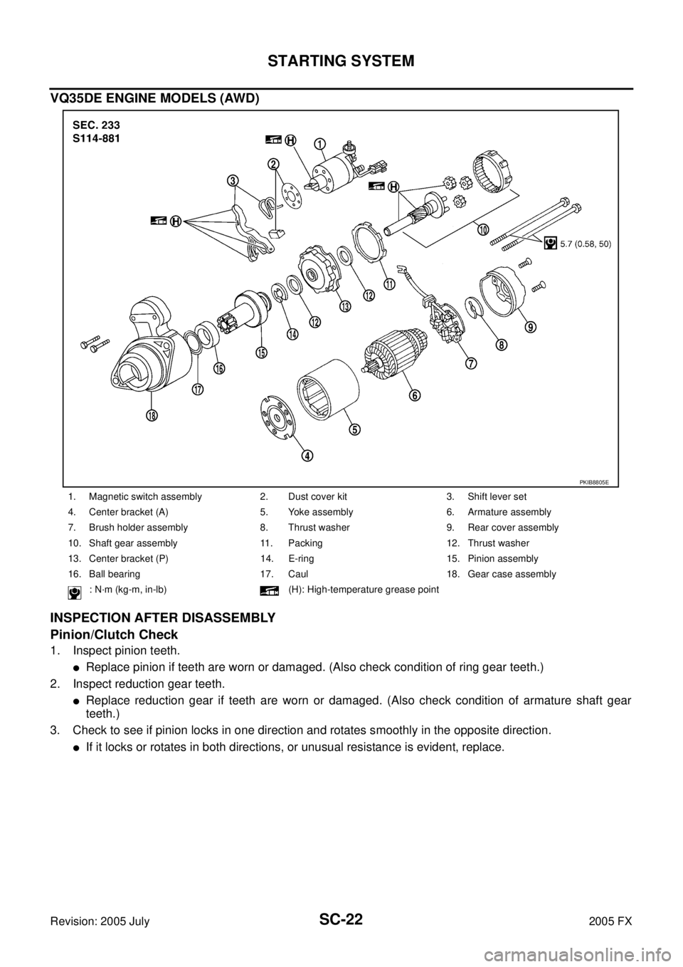
VQ35DE ENGINE MODELS (AWD)
INSPECTION AFTER DISASSEMBLY
Pinion/Clutch Check
1. Inspect pinion teeth.
�Replace pinion if teeth are worn or damaged. (Also check condition of ring gear teeth.)
2. Inspect reduction gear teeth.
�Replace reduction gear if teeth are worn or damaged. (Also check condition of armature shaft gear
teeth.)
3. Check to see if pinion locks in one direction and rotates smoothly in the opposite direction.
�If it locks or rotates in both directions, or unusual resistance is evident, replace.
1. Magnetic switch assembly 2. Dust cover kit 3. Shift lever set
4. Center bracket (A) 5. Yoke assembly 6. Armature assembly
7. Brush holder assembly 8. Thrust washer 9. Rear cover assembly
10. Shaft gear assembly 11. Packing 12. Thrust washer
13. Center bracket (P) 14. E-ring 15. Pinion assembly
16. Ball bearing 17. Caul 18. Gear case assembly
: N·m (kg-m, in-lb) (H): High-temperature grease point
PKIB8805E
Page 4480 of 4731

80845-71L00: 30 mm (1.18 in) thick, 30 × 50 mm (1.18 × 1")
SQUEAK AND RATTLE TROUBLE DIAGNOSIS SE-7
C
D E
F
G H
J
K L
M A
B
SE
Revision: 2005 July 2005 FX
INSULATOR (Light foam block)
80845-71L00: 30 mm (1.18 in) thick, 30 × 50 mm (1.18 × 1.97 in)
FELT CLOTHTAPE
Used to insulate where movement does not occur.Ideal for instrument panel applications.
68370-4B000: 15 × 25 mm (0.59 × 0.98 in) pad/68239-13E00: 5 mm (0.20 in) wide tape roll
The following materials, not found in the kit, can also be used to repair squeaks and rattles.
UHMW (Teflon) TAPE
Insulates where slight movement is present. Ideal for instrument panel applications.
SILICONE GREASE
Used in place of UHMW tape that will be visible or not fit.
Note: Will only last a few months.
SILICONE SPRAY
Use when grease cannot be applied.
DUCT TAPE
Use to eliminate movement.
CONFIRM THE REPAIR
Confirm that the cause of a noise is repaired by test driving the vehicle. Operate the vehicle under the same
conditions as when the noise originally occurred. Refer to the notes on the Diagnostic Worksheet.
Generic Squeak and Rattle TroubleshootingAIS002WY
Refer to Table of Contents for specific component removal and installation information.
INSTRUMENT PANEL
Most incidents are caused by contact and movement between:
1. The cluster lid A and instrument panel
2. Acrylic lens and combination meter housing
3. Instrument panel to front pillar garnish
4. Instrument panel to windshield
5. Instrument panel mounting pins
6. Wiring harnesses behind the combination meter
7. A/C defroster duct and duct joint
These incidents can usually be located by tapping or moving the components to duplicate the noise or by
pressing on the components while driving to stop the noise. Most of these incidents can be repaired by apply-
ing felt cloth tape or silicon spray (in hard to reach areas). Urethane pads can be used to insulate wiring har-
ness.
CAUTION:
Do not use silicone spray to isolate a squeak or rattle. If you saturate the area with silicone, you will
not be able to recheck the repair.
CENTER CONSOLE
Components to pay attention to include:
1. Shifter assembly cover to finisher
2. A/C control unit and cluster lid C
3. Wiring harnesses behind audio and A/C control unit
The instrument panel repair and isolation procedures also apply to the center console.
DOORS
Pay attention to the:
1. Finisher and inner panel making a slapping noise
2. Inside handle escutcheon to door finisher
3. Wiring harnesses tapping
4. Door striker out of alignment causing a popping noise on starts and stops
Tapping or moving the components or pressing on them while driving to duplicate the conditions can isolate
many of these incidents. You can usually insulate the areas with felt cloth tape or insulator foam blocks from
the Nissan Squeak and Rattle Kit (J43980) to repair the noise.
Page 4485 of 4731
SE-12
AUTOMATIC DRIVE POSITIONER
Revision: 2005 July 2005 FX
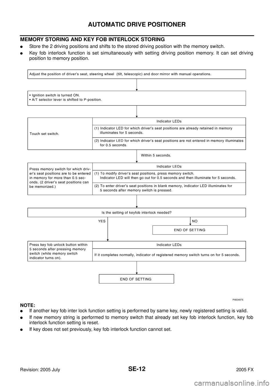
MEMORY STORING AND KEY FOB INTERLOCK STORING
�Store the 2 driving positions and shifts to the stored driving position with the memory switch.
�Key fob interlock function is set simultaneously with setting driving position memory. It can set driving
position to memory position.
NOTE:
�If another key fob inter lock function setting is performed by same key, newly registered setting is valid.
�If new memory string is performed to memory switch that already set key fob interlock function, key fob
interlock function setting is reset.
�If key does not set previously, key fob interlock function cannot set.
PIIB3487E
Page 4487 of 4731

SE-14
AUTOMATIC DRIVE POSITIONER
Revision: 2005 July 2005 FX
KEY FOB INTERLOCK OPERATION
�Perform memory operation, exiting operation and entry operation by pressing key fob unlock button.
NOTE:
�If steering wheel operation is cancelled, the system performs seat and mirror operation only.
�If Entry/Exiting operation is cancelled, the system performs steering wheel operation and mirror operation
only.
�If ignition switch turns ON in the middle of memory operation, the system does not perform exiting opera-
tion after memory operation.
�If ignition switch turns ON in the middle of exiting operation, entry operation starts at that time.
FAIL - SAFE MO DE
When any manual and automatic operations are not performed, if any motor operations of seats or tilt of steer-
ing are detected for approx. 0.1 sec or more, status is judged “Output malfunction”. Motor operation will be
suspended automatically, and all automatic operations will be ineffective (in this case, the motor will not oper-
ate manually).
CANCEL OF FAIL-SAFE MODE
�The mode is cancelled when the selector lever is shifted to P position from any other position.
PIIA6949E
OPERATED PORTION Seat sliding
Seat reclining
Seat lifting (Front)
Seat lifting (Rear)
steering tilt
steering telescopic


1. Magnetic switch assembly 2. Dust cover kit 3. Shift lever set
4. Center bracket")